Band 2 Preamplifier
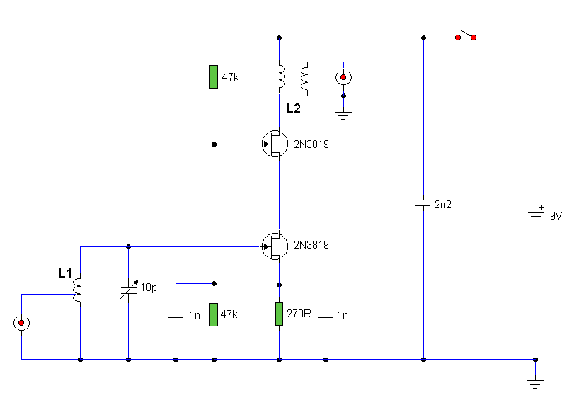
The circuit utilizes two 2N3819 FETs arranged in a cascode configuration. The lower FET functions in common source mode, while the upper FET operates in common gate mode, achieving full high-frequency gain. The lower FET is tunable, enabling peak tuning for a specific station. Coil details are provided subsequently.
The described circuit employs two 2N3819 Field Effect Transistors (FETs) configured in a cascode arrangement, which is advantageous for enhancing frequency response and gain performance. In this configuration, the lower FET operates in common source mode, which is characterized by its ability to provide significant voltage gain. This stage is crucial for amplifying the input signal before it is passed to the upper FET.
The upper FET, functioning in common gate mode, serves to improve the overall bandwidth of the circuit. This mode is particularly effective at high frequencies, as it provides a low input impedance and high output impedance, allowing for better signal integrity and reduced distortion. The combination of these two modes in a cascode configuration results in a circuit that can handle high-frequency signals with improved gain and stability.
The tunable aspect of the lower FET is essential for applications requiring selective frequency tuning, such as in radio receivers. By adjusting the gate voltage or using a variable resistor in the circuit, the peak gain can be optimized for a specific station frequency, ensuring that the desired signal is amplified while minimizing interference from other frequencies.
Coil details, which are integral to the circuit's tuning capabilities, are critical for determining the resonant frequency and impedance matching of the circuit. The choice of coil inductance and quality factor (Q) will influence the performance characteristics, including selectivity and sensitivity. Properly designed coils will facilitate effective tuning and enhance the overall functionality of the circuit.The circuit uses two 2N3819 FET`s in cascode configuration. The lower FET operates in common source mode, while the upper FET, operates in common gate, realising full high frequency gain. The bottom FET is tunable allowing a peak for a particular station. Coil details follow: 🔗 External reference
