
Band-pass filters
A band-pass filter is a crucial component in many electronic systems, designed to allow signals within a specified frequency range to pass through while attenuating frequencies outside this range. The design typically involves the integration of both low-pass and high-pass filter characteristics, effectively creating a filter that only permits frequencies between a defined lower cutoff frequency (f_L) and an upper cutoff frequency (f_H) to pass.
The implementation of a band-pass filter can be achieved using various methods, including passive components (resistors, capacitors, and inductors) or active components (operational amplifiers in conjunction with passive elements). The choice of components will depend on the specific application requirements, such as the desired bandwidth, insertion loss, and power handling capabilities.
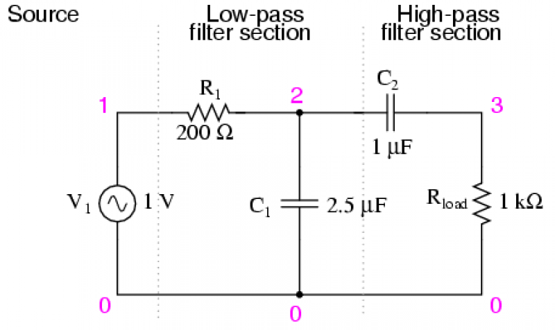
In a basic passive band-pass filter design, the circuit can be structured using a series connection of a high-pass filter followed by a low-pass filter. The high-pass filter is formed by a capacitor (C1) in series with a resistor (R1) to ground, which sets the lower cutoff frequency. The low-pass filter is created by a capacitor (C2) connected in parallel with a resistor (R2), which determines the upper cutoff frequency. The output is taken from the junction between the two filters.
The transfer function of a band-pass filter can be derived from the individual transfer functions of the low-pass and high-pass filters. The bandwidth of the filter is defined as the difference between the upper and lower cutoff frequencies, and the quality factor (Q) can be calculated to assess the selectivity of the filter. A higher Q indicates a narrower bandwidth, which is often desirable in applications requiring precise frequency selection, such as in communication systems, audio processing, and instrumentation.
Block diagrams can effectively illustrate the functional relationships in a band-pass filter circuit, showing the flow of signals through the high-pass and low-pass stages. This visual representation aids in understanding how the filter processes input signals to achieve the desired output characteristics.There are applications where a particular band, or spread, or frequencies need to be filtered from a wider range of mixed signals. Filter circuits can be designed to accomplish this task by combining the properties of low-pass and high-pass into a single filter.
The result is called a band-pass filter. Creating a bandpass filter from a low-pass and high-pass filter can be illustrated using block diagrams 🔗 External reference
Related Circuits
Using a modified equal-element design for a lumped-circuit lowpass filter has several advantages over the well-known equal-element design. The modified design exhibits superior passband performance with only modest degradation of stopband selectivity. Moreover, the modified design is simple and...
A current differencing transconductance amplifier (CDTA) serves as an active component that can be utilized to create various filter responses. The selection of different filter characteristics is achieved by altering the bias current supplied to the amplifier. The current differencing...
This audio noise filter circuit is a bandpass filter designed for the audio frequency range. It effectively filters out unwanted signals that fall outside the audio frequencies. The circuit consists of two filters: a low-pass filter and a high-pass...
The input signal is processed with an electronic low-pass filter to eliminate all frequencies above the Nyquist frequency, which is half of the sampling rate. This process is essential to prevent aliasing during sampling and is referred to as...
One of the limitations affecting all real amplifiers is the finite signal bandwidth. This implies that any amplifier constructed or utilized has an upper limit to the range of sinewave frequencies it can amplify. Consequently, high-frequency signals may not...
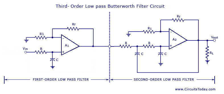
From the discussion made so far on the filters, it can be concluded that in the stopband, the gain of the filter changes at the rate of 20 dB/decade for first-order filters and 40 dB/decade for second-order filters. This...
Warning: include(partials/cookie-banner.php): Failed to open stream: Permission denied in /var/www/html/nextgr/view-circuit.php on line 713
Warning: include(): Failed opening 'partials/cookie-banner.php' for inclusion (include_path='.:/usr/share/php') in /var/www/html/nextgr/view-circuit.php on line 713