
Bar graph LED
The proposed circuit utilizes a 555 timer, a 4029 binary counter, and a 4511 BCD to 7-segment latch/decoder driver, along with a common anode LED bar graph display. The 555 timer can be configured in monostable mode to generate a pulse when a button is pressed, which will serve as a clock signal for the 4029 counter. The 4029 can count in binary or BCD, depending on the configuration, and its outputs will be connected to the inputs of the 4511 decoder. The 4511 will convert the binary input from the 4029 into a format suitable for driving the common anode LED bar graph, lighting up the appropriate segments corresponding to the count.
Due to the nature of common anode displays, the positive terminals of all LEDs will be connected to the power supply, while the negative terminals will need to be controlled through the 4511 outputs. To achieve this, an inverter or a simple logic level change can be used to ensure that the correct segments light up when the output from the 4511 goes low. This can also be accomplished by reconfiguring the logic of the pushbutton inputs to accommodate the common anode setup.
Testing the circuit incrementally is crucial. Initially, the 4511 can be tested with a few LEDs to visualize the output for specific counts. Once this is verified, the 4029 can be integrated, ensuring that the button press correctly increments the count displayed on the bar graph. Each component should be checked for functionality before combining them into the final circuit, ensuring that all connections are made securely and correctly to avoid any potential issues during operation.
This project not only serves as a practical application of fundamental electronic principles but also provides an opportunity to explore the interactions between different types of components, enhancing the understanding of digital electronics.Using a 555 with perhaps a 4029, and I would add a 4511, then connect the pins (using resistors of course), of the bargraph leds, to "a-g" pins of the 4511. To top it all off the graphs I received are all common anode, which is a pain because I`m not too savy like that.
I know what a 555 timer is but I wouldn`t have a clue as to wire them with what as was suggested here. Let alone to make it so it increments with each button press. well, I breadboarded everything but I couldn`t get the damn thing to work. Don`t know if I missed a connection somewhere or what, but no joy all the way. To top it all off the graphs I received are all common anode, which is a pain because I`m not too savy like that. I know what a 555 timer is but I wouldn`t have a clue as to wire them with what as was suggested here.
Let alone to make it so it increments with each button press. Sounds great man. At this point it`s more of a learning experience for me than anything else; and if others can learn something to then great! I`ll shoot ya a PM with what I want but in a nutshell I`ve got some anode common LED bar graphs that I`d like to increment with a button.
It`s probably easier to wire up than I`m thinking about. Edit: Also, is this a screen prop that will appear on camera It`s slightly easier to do if it is acceptable that the LEDs may shimmer slightly when shown on video. Edit edit: And what d`you want to run it from Three AA cells is easiest from an engineering point of view, as the micro is a 5V device (that will tolerate 4.
5) Thank-you for your offer Hfuy but using logic gates are a great way to learn some circuitry. I`ve got an Arduino but I find the circuits themselves fascinating in their own right and would just love to get a handle on them. One of those crawl before you walk things you know Common anode displays are going to make it slightly more complicated, but it shouldn`t be the end of the world.
It simply means that all the positive ends of the LEDs are connected together, and you need to control the display by connecting its negative ends to ground. You can do this using inverter chips on the output of your existing logic circuitry, although you could also just reverse the sense of your "up" and "down" buttons and flip the display over to get the same result.
The way to prototype this sort of thing is to do it block by block and test each part works before you move on. For instance, if you used the 4510 BCD counter, you could put four LEDs on its outputs (with suitable series resistors) and watch it count in binary, to ensure you`d got that bit right.
I don`t know what you`ve bought, but you might want to try that in the first instance. Then you can add the other parts. The only thing that confuses me is the constant reference to 555 oscillators in this thread. The 555 is a timing device that`s very often used in situations where you want a running sequence of lights. I suspect a lot of real Star Trek hand props used exactly the sort of 555/4017 combinations that are being proposed here - the tricorders, etc - if they didn`t do it with micros.
The thing is, you don`t want a constant running sequence, you want a sequence that steps up or down when you press a button. That being the case, you don`t need something that has a 555 in it. Just connecting a pushutton (via suitable debouncing circuitry ) to the clock input of the 4017 will make it step up once every time you hit the button, which is sort of half of what you probably want.
As we discussed before, there are imperfections with this simple approa 🔗 External reference
Related Circuits
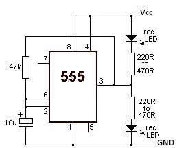
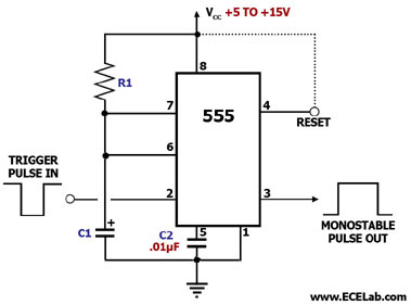
This LED flasher circuit utilizes a 555 timer integrated circuit (IC). The circuit diagram is straightforward and requires only a few external components. When operational, the red LEDs will flash sequentially at a predetermined frequency, similar to the indicators...
Switching to alternative power sources can help reduce electricity bills. The photovoltaic module or solar panel described here is capable of generating renewable energy. The photovoltaic module, commonly known as a solar panel, is a device that converts sunlight into...
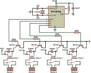
This is a relay driver based on a PIC16F84A microcontroller. The board includes four relays, allowing control of four distinct outputs. The relay driver circuit utilizing the PIC16F84A microcontroller is designed for controlling multiple devices or systems through relay activation....
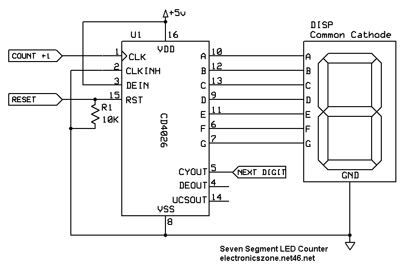
This circuit counts pulses on a seven-segment display using the 4026 counter chip. It is easily expandable for multi-digit counting. The circuit utilizes the 4026 integrated circuit, which is a decade counter specifically designed to drive a seven-segment display. The...
A peak level indicator when a signal exceeds a certain maximum value. It can be quite useful, for instance, with tape recorders, mixing consoles etc. One of the most important requirements of a peak level indicator is that it...
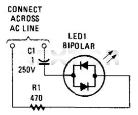
Many electronic circuits require an indication that they are powered. For most AC circuits, a neon lamp is the preferred device. A bidirectional tricolor LED can also be utilized if a capacitor is connected in series with the LED...