
Basic Multimeter
The multimeter described is designed to be a versatile instrument for measuring electrical parameters across a wide range of applications. The core functionality is based on the combination of a basic meter movement and selectable resistive components, which allow it to adapt to different measurement requirements. The use of shunts enables the meter to measure larger currents than its inherent capacity, while series resistors are employed to select voltage ranges.
The first unit of the multimeter is equipped with a 0-1 mA meter movement, which serves as the primary measurement element. This movement is sensitive enough to detect small variations in current, making it suitable for low-level measurements. The inclusion of switches allows for the selection of various shunt resistors, enabling the user to scale the measurement range. The six current ranges extend up to 1 amp, making the instrument suitable for a variety of applications, from laboratory experiments to fieldwork.
The voltage measurement capability of the multimeter is enhanced by the inclusion of eight DC voltage ranges, capable of measuring up to 1000 volts. This wide range is particularly useful in electrical troubleshooting and testing scenarios. The internal battery provides the necessary power for the ohms measurement function, allowing for resistance measurements up to 200,000 ohms, which is essential for assessing the integrity of components and circuits.
The add-on unit further expands the multimeter's functionality by incorporating a meter rectifier, which allows for the measurement of AC voltages. This feature is crucial for applications where AC measurements are required, such as in power systems or electronic devices. The additional shunt and series resistors (Ra and Rb) provide the capability to measure higher currents (up to 10 A) and voltages (up to 5 kV), making the multimeter suitable for high-power applications as well.
The precision of the measurements is ensured by using high-stability resistors with a tolerance of 1%. The choice of Eureka wire for the shunts is significant, as it offers low temperature coefficients and stable resistance values over a range of conditions. The design allows for experimental adjustment of shunt values, ensuring that the multimeter can be calibrated accurately against a known reference meter.
In summary, this multirange multimeter design is characterized by its flexibility, accuracy, and the ability to measure a wide range of electrical parameters, making it an invaluable tool for engineers, technicians, and hobbyists alike.A number of shunts and multipliers selected by a switch can be used in association with a single basic meter to form a multirange instrument, known as a multimeter. this is capable of measuring volts, current and resistance. A multirange meter can be constructed in two units, the first containing the 0-1mA meter movement with switches to select va
rious shunt and series resistors to give six d. c. current ranges up to 1 amp and eight d. c. voltage ranges up to 1000 volts. An internal battery provides an ohms range readable up to 200, 000 ohms which corresponds with the first division of the meter (0. 02mA) An Add-on unit contains a meter rectifier with associated switched series resistors to give four a.
c. voltage ranges up to 100 volts while additional shunt and series resistors (Ra and Rb) extend the range to 10A and 5Kv. When using the add-on unit the main instument is set to measure 1mA FSD and the add-on unit is connected to its terminals by its lugs.
The series resistors are 1% tolerance high stability types while the shunts are made of lengths of Eureka resistance wire. The wire used on electric fire elements is ideal for the lower value shunts. The values have been calculated for a meter resistance of 60 ohms internal resistance but would need modifying for other values.
In any case, the precise value of each shunt should be adjusted experimentally to give the correct reading against a meter of known accuracy. For example: If a milliammeter of 10 ohms resistance and a FSD of 1mA is to be used to measure 100mA, a shunt must be provided to carry the excess current, that is 100-1 milliamps, i.
e 99mA. Thus the required shunt resistance is: 🔗 External reference
Related Circuits

A basic LED driver circuit consists of a 5-volt power source, a 2 kΩ potentiometer, and an LED. The LED is forward biased, with the manufacturer specifying a maximum current rating of 20 mA at a diode voltage drop...
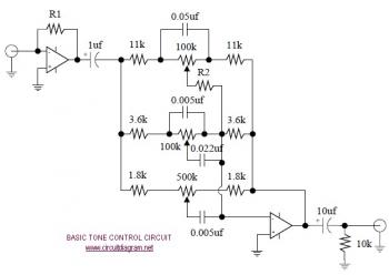
The following diagram illustrates the schematic of an Active Tone Control circuit, commonly referred to as "ACTOR." The ACTOR is an electronic audio circuit designed to enhance loudness by adjusting bass and treble audio signals. It operates using the...
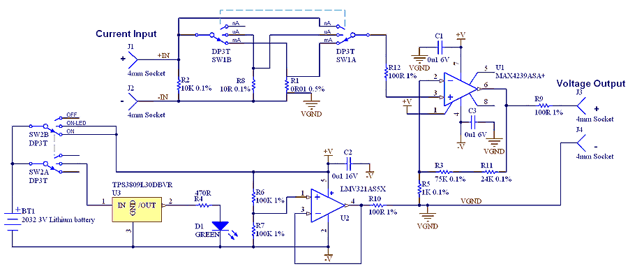
The µCurrent is in many cases also able to improve upon your meters current range accuracy by using your meters more accurate mVDC or mVAC voltage ranges instead to display the DC or AC current. With AC the frequency...
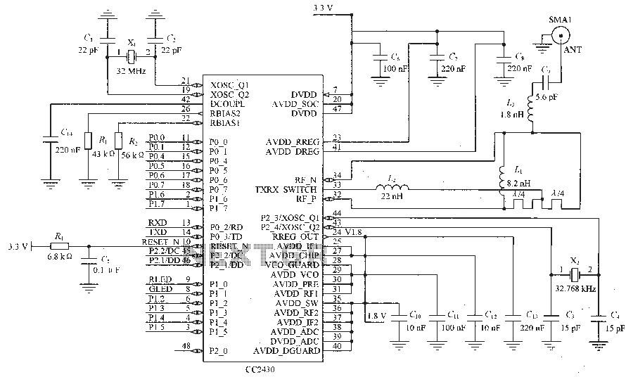
Figure C1 and C2 depict a 22 pF capacitor connected to a 32 MHz crystal oscillator circuit, which utilizes a quartz crystal for standard operation. Capacitors C3 and C4, each rated at 15 pF, are connected to a 32.768...
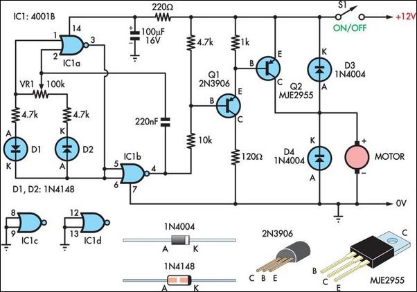
Two simple 12V DC motor speed controllers can be constructed for a minimal cost. These controllers take advantage of the principle that the rotational speed of a DC motor is directly proportional to the average value of its supply...
A diode for alternating current is a trigger diode that conducts current only after the DIAC reaches the breakdown voltage. The breakdown voltage of the DIAC is 30 V. A DIAC, or Diode for Alternating Current, is a semiconductor device...
Warning: include(partials/cookie-banner.php): Failed to open stream: Permission denied in /var/www/html/nextgr/view-circuit.php on line 713
Warning: include(): Failed opening 'partials/cookie-banner.php' for inclusion (include_path='.:/usr/share/php') in /var/www/html/nextgr/view-circuit.php on line 713