
Basic reference transistor bias circuit - Mixed Negative feedback
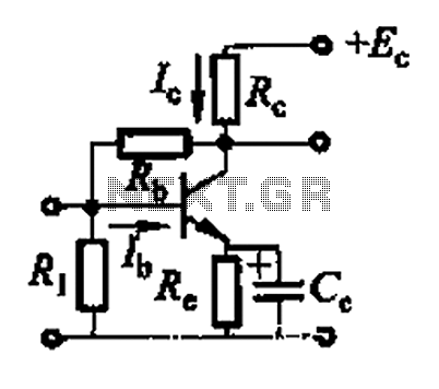
The basic reference transistor bias circuit utilizing mixed negative feedback is a fundamental electronic configuration designed to stabilize the operating point of a transistor. This circuit typically employs a combination of resistive feedback and emitter degeneration to enhance linearity and thermal stability.
In this configuration, a transistor is connected in a common-emitter arrangement, where the input signal is applied to the base terminal. The collector is connected to a power supply, while the emitter is connected through a resistor to ground. The mixed negative feedback is achieved by incorporating resistors that connect the collector to the base, providing a fraction of the output voltage back to the input. This feedback mechanism helps to reduce the gain sensitivity to variations in transistor parameters and temperature changes.
The biasing network is crucial for ensuring that the transistor operates in the active region, preventing it from entering saturation or cutoff during signal variations. The design of the resistor values is critical, as they determine the biasing current and, consequently, the quiescent point (Q-point) of the transistor. Proper selection of these components allows for a stable operation over a range of conditions, making this circuit widely used in amplifier designs and other applications requiring reliable transistor performance.
In summary, the basic reference transistor bias circuit with mixed negative feedback is essential for achieving stable and linear transistor operation, which is vital for a variety of electronic applications. Basic reference transistor bias circuit - Mixed Negative feedback
Related Circuits
This circuit can be adapted for other regulated and unregulated voltages by using different regulators and batteries. For a 15 Volt regulated supply use two 12 Volt batteries in series and a 7815 regulator. There is a lot of...
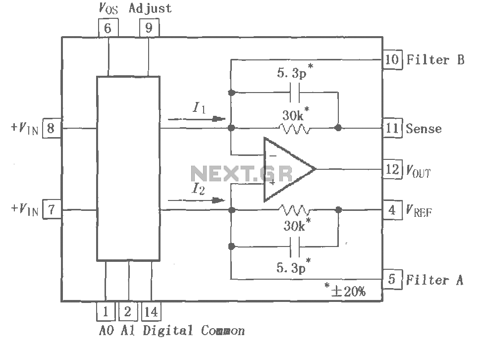
The PGA202 is a digitally controlled programmable gain amplifier with gain settings of G = 1, 10, 100, and 1000. The PGA203 offers gain settings of G = 1, 2, 4, and 8. Both amplifiers are compatible with CMOS...
This is an enhanced infrared (IR) remote control extender circuit that exhibits high noise immunity, resistance to ambient and reflected light, and an extended operational range of approximately 7 meters between the remote control and the extender circuit. It...
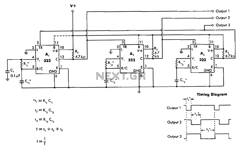
The 322 monostable multivibrator is configured in a cross-connected manner. When operating under non-steady state conditions with the oscillator Unicom, it generates a continuous timing cycle, as illustrated in the accompanying figure. T represents the total time period of...
This circuit is essentially a crystal radio equipped with an audio amplifier that demonstrates considerable sensitivity, successfully receiving multiple strong stations in the Los Angeles area using a minimal 15-foot antenna. Employing a longer antenna can enhance signal strength;...
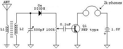
The following schematic illustrates a Crystal Radio Receiver Circuit Diagram that incorporates audio frequency (AF) amplification utilizing a Germanium transistor. The inclusion of AF amplification enhances the audio output quality. The Crystal Radio Receiver Circuit is a simple yet effective...
Warning: include(partials/cookie-banner.php): Failed to open stream: Permission denied in /var/www/html/nextgr/view-circuit.php on line 713
Warning: include(): Failed opening 'partials/cookie-banner.php' for inclusion (include_path='.:/usr/share/php') in /var/www/html/nextgr/view-circuit.php on line 713