
Basic RF Oscillator
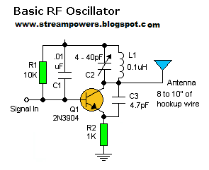
To implement a circuit capable of receiving the specified FM signal, a standard FM radio receiver can be utilized. The coupling of the signal to the main stage of the receiver is achieved through a disc capacitor, which is selected to have a capacitance value of approximately 0.1 µF.
In this configuration, the disc capacitor serves to block any DC component of the incoming signal while allowing the AC component, which carries the information, to pass through. This is crucial for maintaining the integrity of the FM signal during the reception process. The capacitor must be rated to handle the frequency range of the FM broadcast, typically from 88 MHz to 108 MHz, ensuring that it does not introduce excessive loss or distortion.
The main stage of the FM receiver typically includes an RF amplifier, a demodulator, and an audio amplifier. The RF amplifier boosts the weak incoming signal, improving the overall sensitivity of the receiver. The demodulator then extracts the audio information from the modulated carrier wave, converting it into an audio signal that can be amplified further by the audio amplifier for playback through speakers or headphones.
Proper grounding and shielding are essential in this circuit to minimize noise and interference, which can degrade the quality of the received signal. Additionally, the layout of the circuit should be designed to reduce parasitic capacitance and inductance, which can affect the performance of the FM receiver.
In summary, the use of a 0.1 µF disc capacitor for coupling the signal to the main stage of an FM radio receiver is a critical design consideration that ensures effective signal processing and high-quality audio output.You ought be able to pick up its signal with a standard FM radio receiver. The signal in ought be coupled by a disc capacitor of about 0. 1 uF to stage in main of it. 🔗 External reference
Related Circuits
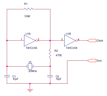
The 74HCU04 is a chip designed for specific circuit applications, while the HCT variant may not be suitable for such configurations. Capacitors C1 and C2 can be utilized up to 33pF, and resistor R2 can be adjusted to achieve...

A Schmitt trigger provides effective squaring of the output, sometimes eliminating the need for an additional output stage. A Schmitt trigger is a type of comparator circuit that incorporates hysteresis, which allows it to provide clean, stable output transitions. This...
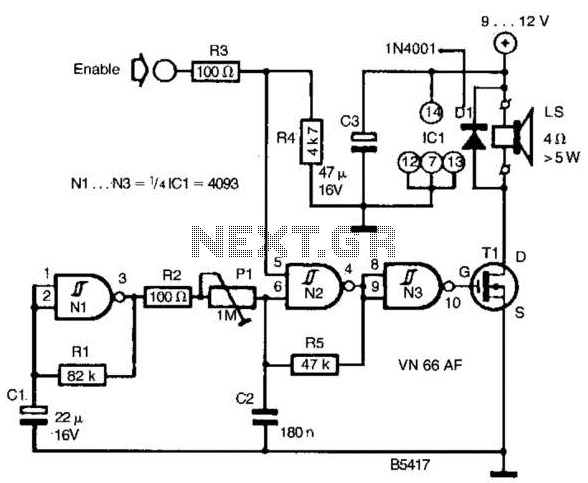
A CD4093 chip and several components form a siren oscillator that drives power MOSFET Tl. A speaker is directly powered by this device. The siren is activated by a logic high signal applied to the ENABLE input. The circuit comprises...
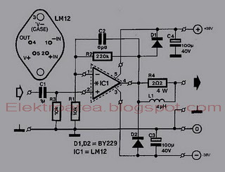
This is an 80W power amplifier OCL circuit that utilizes the integrated circuit LM12. It effectively enhances bass and treble performance. When connected to a CD player, it produces high-quality sound, especially when paired with a good pre-tone control....
Using two gates from a CMOS 4011 NAND chip, a simple square wave oscillator can be made. Alternatively, a CMOS 4001 chip can also be used, or a TTL equivalent. In this circuit, the mark-space ratio can also be...
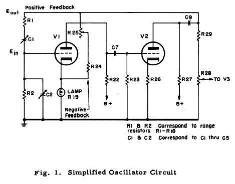
After repairing several Hewlett Packard vacuum tube voltmeters, research was conducted on the company's history. An HP-200C oscillator was located, which closely resembles the company's initial product. It is a Wien bridge resistance-tuned oscillator featuring a light bulb stabilized...