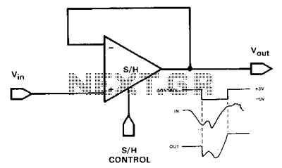
Basic-track-and-hold-sample-and-hold

Feedback operates similarly to a conventional operational amplifier (op-amp) voltage follower, providing 11 unity-gain, non-inverting outputs. This configuration also features a very high input impedance. The primary distinction between a track-and-hold and a sample-and-hold lies in the duration for which the switch remains closed. In track-and-hold operation, the switch is closed for a relatively extended period, allowing the output signal to change significantly and maintain the level present at the moment the switch is opened. In sample-and-hold operation, the switch remains closed only for the time required to fully charge the holding capacitor.
The described circuit utilizes an operational amplifier in a feedback configuration, functioning as a voltage follower with a high input impedance, which is advantageous for interfacing with high-impedance signal sources. The op-amp's feedback loop ensures that the output voltage closely follows the input voltage, maintaining unity gain. This characteristic is particularly useful in applications requiring signal buffering without loading effects.
In the context of track-and-hold and sample-and-hold operations, the circuit's performance can be optimized based on the specific application requirements. The track-and-hold mode is suited for capturing rapidly changing signals, as it allows the output to track the input over a longer duration. This is essential in applications such as analog-to-digital conversion, where it is crucial to maintain an accurate representation of the input signal during the conversion process.
Conversely, the sample-and-hold mode is designed for applications where the input signal does not change significantly during the sampling period. The switch in this mode is activated only for the brief duration necessary to charge the holding capacitor, ensuring that the output reflects the input signal accurately at the moment of sampling. This mode is often employed in data acquisition systems where precise timing and signal integrity are paramount.
In both configurations, careful consideration must be given to the selection of components, particularly the op-amp, switch, and holding capacitor, to ensure optimal performance. The op-amp should be chosen based on parameters such as bandwidth, slew rate, and input offset voltage, while the switch must be capable of handling the required signal levels without introducing significant distortion or delay. The holding capacitor's value will directly influence the output signal's stability and response time, necessitating a balance between capacitance and the desired hold time.
Overall, the implementation of track-and-hold and sample-and-hold circuits is critical in various electronic applications, facilitating accurate signal processing and conversion in real-time systems.Feedback is the same as a conventional op-amp voltage follower which yields 11 unity-gain, noninverting output. This hookup also has a very high input impedance. The only difference between a track-and-hold and a sample-and-hold is the time period during which the switch is closed.
In trackand- hold operation, the switch is closed for a relatively long period; the output signal might change appreciably and would hold the level present at the instant the switch is opened. ln sample-and-hold operation, the switch is closed only for the time necessary to fully charge the holding capacitor.