Battery-powered-ground-noise-probe

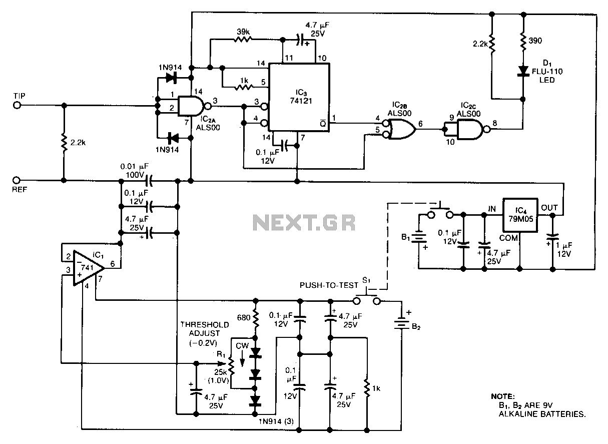
Oscilloscope measurements of ground noise can be unreliable because noise can enter your circuit via the scope's three-pronged power plug. This issue can be mitigated by utilizing the ground-noise tester described. The circuit operates on two 9-V batteries and only consumes power when the push-to-test switch S1 is pressed. Noise pulses that reach the switching threshold of operational amplifier IC2A, approximately 1.5 to 1.8 V, generate a logic transition that activates the monostable multivibrator IC3, extending the pulse duration to create a visible blink from LED D1. The noise reference level is adjustable through the threshold-adjust potentiometer R1, enabling the circuit to respond to minimum pulse amplitudes in the range of about 0 to 1 V. For ease of use, a single-turn potentiometer can be employed for R1, and the dial can be calibrated by applying an adjustable DC voltage, which is monitored using an accurate voltmeter.
The ground-noise tester circuit is designed to enhance the reliability of noise measurements in electronic systems, particularly when using oscilloscopes. The core components include two 9-V batteries that provide the necessary power for circuit operation. The push-to-test switch S1 serves as a control mechanism, allowing the user to activate the circuit only when needed, thus conserving battery life.
Operational amplifier IC2A acts as a comparator that detects noise pulses. When the amplitude of the incoming noise exceeds the predefined threshold of 1.5 to 1.8 V, the output of IC2A transitions, signaling the subsequent component in the signal chain. This transition is crucial as it triggers the monostable multivibrator IC3, which is configured to generate a pulse of a specific duration. The output of IC3 drives LED D1, providing a visual indication of noise detection through a blink, thus allowing users to quickly ascertain the presence of ground noise.
The threshold-adjust potentiometer R1 is instrumental in calibrating the circuit's sensitivity. By adjusting R1, the user can set the minimum pulse amplitude that the circuit will respond to, ensuring flexibility in various measurement scenarios. The use of a single-turn potentiometer simplifies the calibration process. To achieve accurate settings, an adjustable DC voltage can be applied to R1, and the corresponding voltage can be monitored using a precise voltmeter. This calibration step is essential for ensuring that the ground-noise tester operates effectively across different environments and conditions.
In summary, the ground-noise tester circuit is a valuable tool for electronics engineers and technicians, providing a reliable means of assessing and mitigating noise interference in measurement systems. By integrating a simple yet effective design, this circuit enhances the accuracy of oscilloscopic measurements, ultimately leading to improved performance in electronic applications.Oscilloscope measurements of ground noise can be unreliable because noise can enter your circuit via the scope"s three-pronged power plug. You can avoid this problem by using the ground-noise tester shown. Powered by two 9-V batteries, the circuit dissipates power only while push-to-test switch Sl is depressed.
Noise pulses that reach IC2A"s switching threshold of about 1.5 to 1.8 V create a logic transition that triggers the monostable multivibrator IC3, which stretches the pulse to produce a visible blink from LED Dl. You set the noise reference level by adjusting threshold-adjust potentiometer Rl, which lets the circuit respond to minimum pulse amplitudes ranging from about 0 to 1 V. For convenience, you can use a onetum potentiometer for Rl and calibrate the dial by applying an adjustable de voltage, monitored by an accurate voltmeter.
🔗 External reference