
Battery-powered-high-voltage-generator
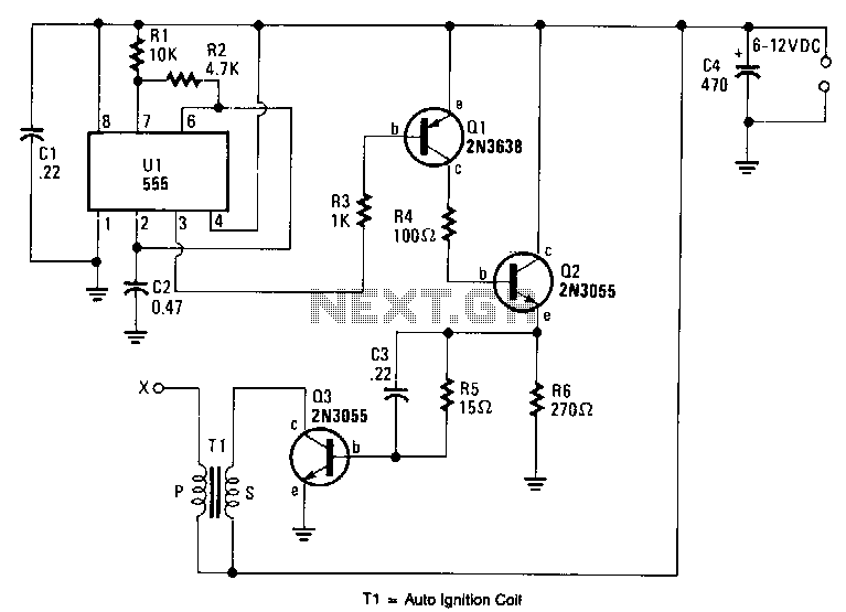
An output voltage sufficient to bridge a one-inch gap can be generated from a 12-V power source. A 555 timer integrated circuit (IC) is configured as an astable multivibrator, producing a narrow negative pulse at pin 3. This pulse activates transistor Q1 for the duration of the timing cycle. The collector of Q1 is directly connected to the base of power transistor Q2, turning it on during the same period. Additionally, the emitter of Q2 is directly connected through a current-limiting resistor R5 to the base of transistor Q3, which switches on, minimizing the resistance between its collector and emitter. The high-current pulse flowing through the primary winding of high-voltage transformer T1 generates a significantly high pulse voltage at its secondary output terminal (labeled X). The pulse frequency is determined by the values of resistors R1, R2, and capacitor C2, which have been selected from the parts list to optimize performance when using an automotive ignition coil for T1.
The circuit operates by utilizing a 555 timer configured in astable mode, creating a continuous square wave output. The frequency of oscillation is influenced by the resistors R1 and R2, along with capacitor C2, which sets the timing intervals for the output pulses. When the 555 timer outputs a negative pulse at pin 3, it triggers transistor Q1, allowing current to flow from the collector to the emitter. This action turns on transistor Q2, which is responsible for driving the current through the primary winding of the transformer T1.
The design incorporates a current-limiting resistor R5, which protects the base of transistor Q3 by controlling the amount of current that can flow into it. When Q2 is activated, it provides sufficient base current to Q3, turning it on and effectively reducing the resistance between its collector and emitter. This configuration allows for a high-current pulse to flow through the primary of transformer T1.
As the current flows through the primary winding of T1, it induces a high voltage in the secondary winding due to the principles of electromagnetic induction. The output from the secondary terminal, labeled X, can reach voltages high enough to create a spark capable of jumping a one-inch gap. This feature makes the circuit suitable for applications such as igniting gas burners or providing spark for ignition systems.
The choice of components, particularly the values of R1, R2, and C2, is critical in achieving optimal performance, especially when interfacing with an automotive ignition coil. These components must be selected to ensure the frequency and pulse width are appropriate for the specific ignition coil being used, maximizing efficiency and effectiveness in generating the desired high-voltage output.Output voltage great enough to jump a l-inch gap can be obtained from a 12-V power source. A 555 timer IC is connected as an astable multivibrator that produces a narrow negative pulse at pin 3. The pulse turns Ql on for the duration of the time period. The collector of Ql is direct-coupled to tbe base of tbe power transistor Q2, turning it on during the same time period.
The emitter of Q2 is direct -coupled through current limiting resistor R5 to the base of the power transistor. Q3 switches on, producing a minimum resistance between the collector and emitter. The high-current pulse going through tbe primary of high-voltage transformer Tl generates a very high pulse voltage at its secondary output terminal (labeled X).
The pulse frequency is determined by tbe values of Rl, R2, and C2. The values given in the parts list were chosen to give the best possible performance when an auto-ignition coil is used for Tl. 🔗 External reference