
Battery Voltage Indicator
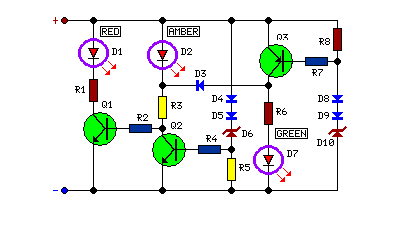
The battery voltage monitoring circuit utilizes a simple yet effective design to provide real-time feedback on the battery's state of charge. The three-LED display typically consists of green, yellow, and red LEDs, each representing different voltage ranges. For instance, the green LED may indicate a voltage level that is within the optimal range, the yellow LED might signal a cautionary level, and the red LED could indicate a low voltage condition that requires immediate attention.
To implement this circuit, a voltage divider may be used to scale down the battery voltage to a level suitable for the LED indicators. A microcontroller or comparator circuit can be employed to interpret the scaled voltage and control the corresponding LED based on predefined voltage thresholds.
The circuit should include a power supply that is capable of operating within the voltage range of the vehicle's battery, typically 12V to 14.4V for standard automotive applications. Additionally, it is advisable to incorporate a fuse for protection against overcurrent conditions, ensuring the longevity and reliability of the circuit.
Overall, this battery voltage monitoring circuit is an essential tool for vehicle maintenance, allowing users to monitor battery health and avoid potential failures due to low voltage conditions.Monitors battery voltage, Three-LED Display Connecting this circuit to the battery of your vehicle, you will always know at a glance the approximate volta.. 🔗 External reference
Related Circuits
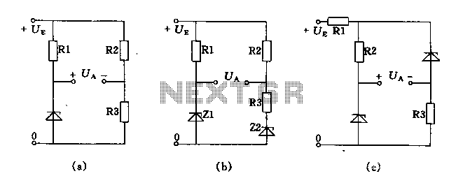
The circuit depicted in Figures A, B, and C demonstrates a high voltage coefficient. When the regulator resistance \( r_z \) is held constant, the bridge configuration achieves an infinite voltage coefficient. In Figure A, the load circuit is...

This circuit is a voltage-controlled oscillator (VCO) that utilizes the 555 timer integrated circuit (IC) as its primary component. The 555 timer is configured as an astable multivibrator, enabling it to function as an oscillator. An astable multivibrator is...
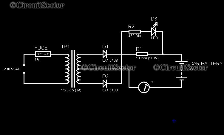
In today's world, owning a car battery charger at home has become essential. Having one readily available can help prevent starting issues caused by battery problems. While purchasing a commercial battery charger can be expensive, the components required for...
The SLA battery is charged from the vehicle's battery. When the engine is running, the voltage remains fairly constant, which greatly simplifies the charging circuit. If the SLA battery is fully charged, any further charging current from the vehicle...
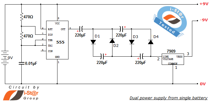
How to create a dual power supply unit using a single battery for laboratory purposes. Dual voltage power supplies are particularly needed for operational amplifier experiments and some instrumentation amplifiers. Additionally, certain low-power audio preamplifiers also require dual voltage...
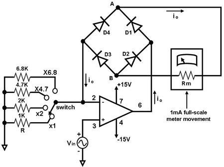
The primary component of this circuit is an operational amplifier (such as the 741 or 351), configured as an amplifier with a feedback circuit that consists of a diode bridge full-wave rectifier. An ammeter is connected to the rectifier...