
Battery Voltage monitor
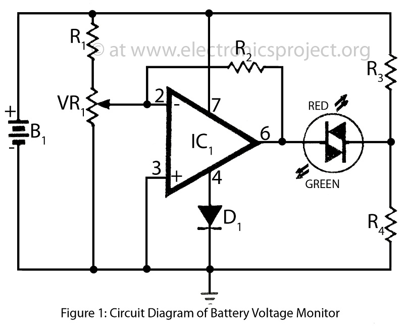
The battery voltage monitor circuit is designed to provide a visual representation of the voltage level of a 12-volt battery, which is commonly used in various applications such as automotive systems, renewable energy storage, and portable electronic devices. This circuit typically incorporates a voltage divider, which scales down the battery voltage to a lower level suitable for measurement by an analog-to-digital converter (ADC) or a microcontroller.
Key components of the circuit may include resistors, an operational amplifier (op-amp), and a display element such as an LED or an LCD screen. The voltage divider consists of two resistors connected in series, where the output voltage is taken from the junction between the two resistors. This output voltage can then be fed into the ADC of a microcontroller, which converts the analog voltage to a digital value for processing.
The op-amp can be used to amplify the voltage signal if necessary, ensuring that the measurement is accurate and within the operational range of the ADC. Additionally, the circuit may include protection features such as fuses or diodes to prevent overvoltage or reverse polarity conditions that could damage the components.
The display element provides a user-friendly interface, allowing users to easily read the battery voltage level. In more advanced designs, the circuit may also include features such as low battery alerts, data logging capabilities, or connectivity options for remote monitoring.
Overall, the battery voltage monitor circuit plays a crucial role in ensuring the reliable operation of battery-powered systems by providing real-time voltage information and enabling proactive maintenance.Battery Voltage monitor is used to indicate the voltage level of 12 volt battery circuit of battery voltage monitor verified electronics project circuit with description. 🔗 External reference
Related Circuits
The voltage reference circuit detailed below is a specialized implementation of the LM334 current source. It is characterized by a very low temperature coefficient for the output voltage and consumes only 10 µA at room temperature. This current may...
A small Tesla Coil (12-inch range), Jacob's Ladder, or an "Antigravity Project" from the book "Electronic Gadgets for the Evil Genius" is being discussed, but sourcing parts for these projects has proven challenging. The book is informative, yet the...
The PTB78560x is a series of 30 W rated isolated DC/DC converters designed to operate from a standard 24 V or 48 V telecom central office (CO) supply. Housed in a 12 package, each model features a wide adjustable...
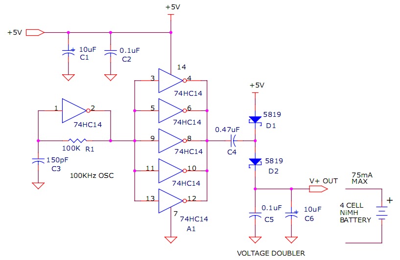
The circuit described will trickle charge a four-cell pack of AA or AAA NiMH batteries. It draws current from the +5V available from a USB connection and supplies approximately 70mA of current to the battery. This current level is...
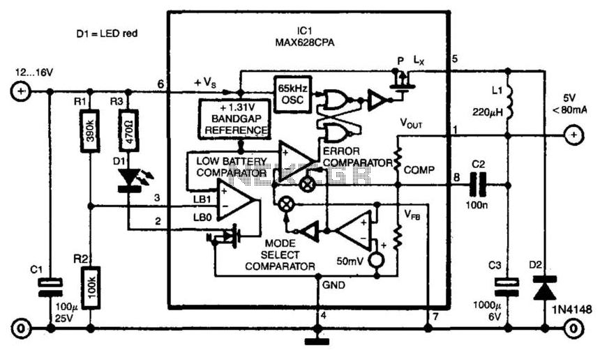
Switch-mode power supplies offer significantly greater efficiency compared to traditional power supplies. The switch-mode regulator described here achieves an efficiency of approximately 85%. It converts an input voltage range of 12 to 16 VDC into a stable output voltage...

The CMOS 4001 consists of four independent two-input NOR gates. These gates are organized into two pairs. Gates 1 and 2 are connected to form a latching circuit. When the alarm is triggered, they will latch and activate the...
Warning: include(partials/cookie-banner.php): Failed to open stream: Permission denied in /var/www/html/nextgr/view-circuit.php on line 713
Warning: include(): Failed opening 'partials/cookie-banner.php' for inclusion (include_path='.:/usr/share/php') in /var/www/html/nextgr/view-circuit.php on line 713