
Beam-break Detector For Camera Shutter or Flash Control
This infrared beam break detection circuit is designed for applications where reliable object detection is required while minimizing the influence of ambient light. The choice of the Jaycar ZD-1942 IR receiver IC is significant due to its capability to maintain a high output signal in the presence of modulated IR light, which is essential for effective operation in various lighting conditions.
The LM7555 timer IC (IC2) operates in monostable mode, meaning it produces a single pulse output when triggered. This feature is particularly useful for applications where a brief response is needed, such as turning off an LED or activating a relay. The timing interval can be fine-tuned to suit specific requirements, allowing flexibility in the duration that the relay remains activated after the beam is interrupted.
The circuit’s power supply, utilizing six AA batteries and a 78L05 voltage regulator, ensures a stable 5V output necessary for the operation of the receiver and timer ICs. The use of a low-power relay allows for controlling higher power loads without significant power drain from the batteries, making the circuit suitable for battery-operated applications.
The transmitter circuit, also based on the LM7555, operates in astable mode, generating a continuous square wave output at a frequency set to 38kHz. This frequency is commonly used in IR remote control systems, ensuring compatibility with a wide range of IR receivers. The adjustable frequency via trimpot VR1 allows for fine-tuning of the modulation, which can help optimize performance based on specific environmental conditions.
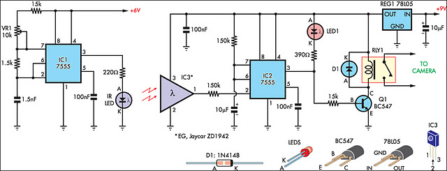
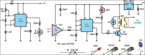
Overall, this circuit provides a robust solution for beam break detection, with a focus on minimizing false triggers caused by ambient light and ensuring reliable operation over several meters. The design considerations, including the choice of components and the configuration of the transmitter and receiver, contribute to its effectiveness in diverse applications.This circuit is presented as an alternative to the IR beam break detector featured in the June 2009 issue (Silicon Chip). In order to make it relatively insensitive to ambient light, it uses a standard IR receiver IC such as the Jaycar ZD-1942.
This has a high output (+5V) as long as a modulated beam is detected. The IR detector (IC3) controls an LM 7555 CMOS timer (IC2) which operates in mono stable mode. When the beam is broken, IC2 is triggered and its pin 3 output goes high for about half a second. This extinguishes LED1 and turns on transistor Q1 to drive a 5V low-power relay. The circuit is powered from six AA cells and a 78L05 5V regulator (necessary for the receiver IC). The IR transmitter is also built around an LM7555 (IC1), this time operating in astable mode at low duty cycle. Its frequency is set to 38kHz with trimpot VR1. The IR diode was salvaged from a defunct remote control but these are readily available new. The transmitter is powered by four AA cells. The system has a range of several metres and while it is insensitive to the transmitter alignment, the detection window can be narrowed by placing the detector near to the object to be detected and/or using some form of baffle to restrict the window.
🔗 External reference
Related Circuits
This circuit is designed to indicate through a flashing LED when room noise exceeds a predetermined threshold, selectable from three fixed levels: 50, 70, and 85 dB. Two operational amplifiers (op-amps) are utilized to amplify the sound captured by...
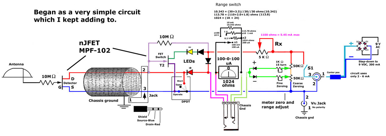
This post discusses the construction of multiple versions of JFET static charge detectors, highlighting observed differences that are not easily explained. The JFET (Junction Field Effect Transistor) static charge detector operates by utilizing the unique characteristics of JFETs to sense...
The IR detector (IC3) controls an LM 7555 CMOS timer (IC2) operating in monostable mode. When the beam is interrupted, IC2 is triggered, and its pin 3 output goes high for approximately half a second. This action extinguishes LED1...
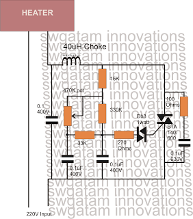
Controlling heaters rated up to 1500 watts requires stringent specifications for the controlling unit to ensure safe and effective operation. The introduction of advanced snubber-less Triacs and Diacs has made it relatively easier to implement heater controllers at high...
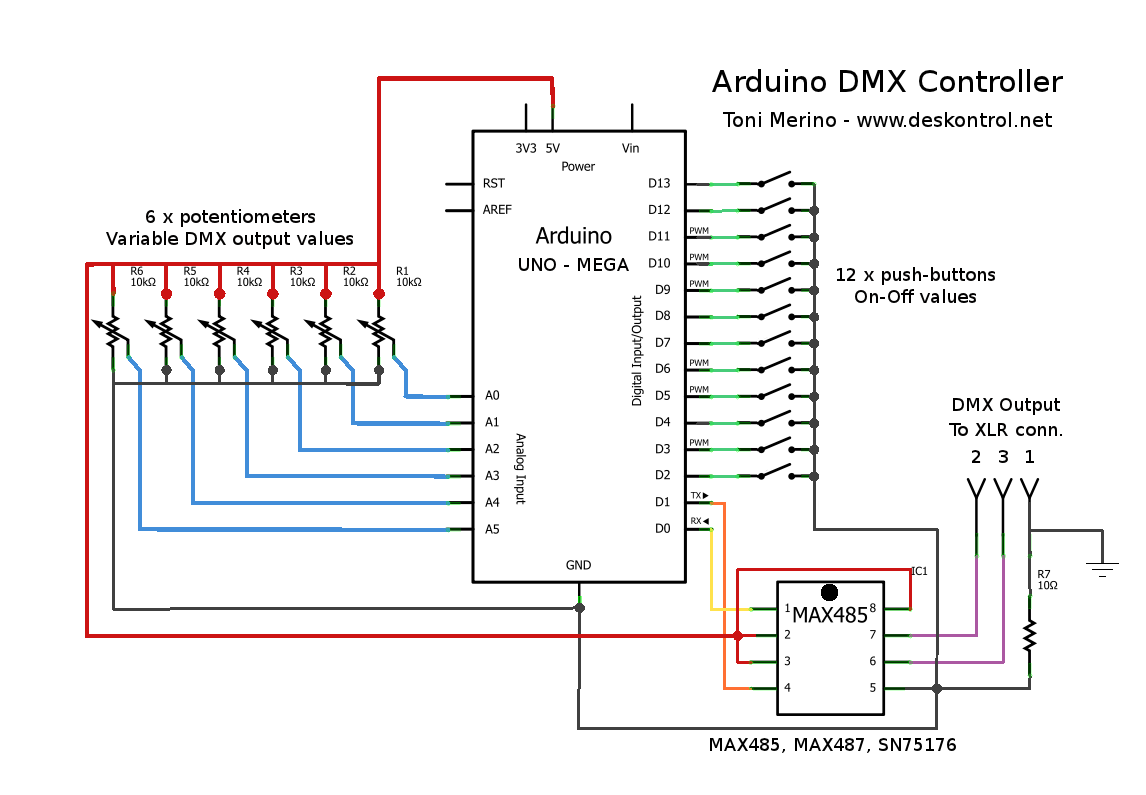
This document outlines the process of creating a compact and efficient Arduino DMX512 controller, which can be utilized to operate devices like a smoke machine via DMX or serve as testing equipment. The configuration includes six channels controlled by...
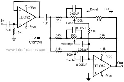
This topic continues the coverage of audio tone controls. The first entry started with a passive tone control circuit using different RC filter configurations and introduced an active filter. The second entry showed a fully designed 2-band active tone...