
become a VU meter and homemade rhythm lights easy [megapost]
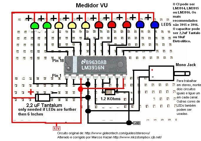
The project involves designing and constructing a visual audio level meter (VU meter) that responds to sound levels, as well as rhythm lights that flash in sync with music or audio signals. The VU meter can be created using a microcontroller, such as an Arduino, which processes audio input and drives LED indicators to reflect the amplitude of the sound.
To begin, the circuit requires an audio input source, which can be connected via a 3.5mm audio jack. An operational amplifier (op-amp) can be used to amplify the audio signal before it is fed into the microcontroller's analog input pin. The microcontroller will then convert the analog signal into a digital value, allowing it to determine the sound level.
For the visual output, a series of LEDs can be arranged in a bar graph format. Each LED will represent a different level of audio intensity, with the microcontroller controlling which LEDs are illuminated based on the processed audio signal. The code running on the microcontroller will include algorithms to smooth out the signal and provide a more visually appealing response, such as fading effects or dynamic flashing patterns.
In addition to the VU meter, the rhythm lights can be implemented using a similar approach. By utilizing a separate set of LEDs, the circuit can be designed to flash in response to specific frequencies or beats detected in the audio input. This can be achieved through frequency analysis, where the audio signal is processed to identify peaks in specific frequency ranges, triggering the corresponding lights to flash in rhythm with the music.
Overall, this DIY project combines basic electronics, programming, and audio processing to create an engaging visual display that enhances the experience of listening to music. The simplicity of the components and the accessibility of microcontrollers make this project suitable for hobbyists and beginners in electronics.Post related to Do it yourself about become a VU meter and homemade rhythm lights easy.. 🔗 External reference
Related Circuits
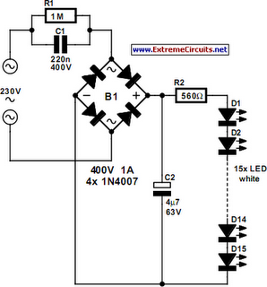
An array of white LEDs can serve as a small lamp for the living room. LED lamps are readily available, resembling standard halogen lamps, and can be installed in a standard 230-V light fixture. A capacitor is employed to...
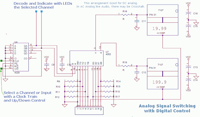
This circuit utilizes a 4052 as a DC Analog Multiplexer. The inputs to this multiplexer must originate from low-impedance output operational amplifiers (OpAmps). The resistors depicted are unnecessary once the signal conditioning OpAmps are connected. However, 100K resistors can...
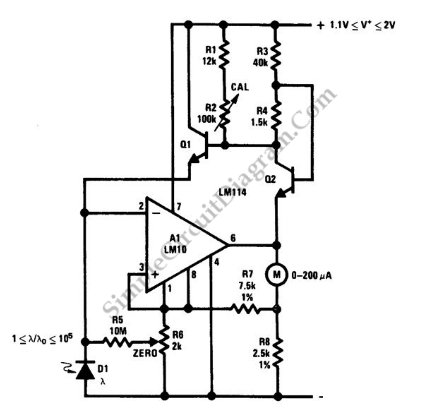
This is a portable light-level meter circuit with a five-decade dynamic range. It utilizes a single-cell battery as the power supply. To calibrate this circuit, The portable light-level meter circuit is designed to measure light intensity across a wide...
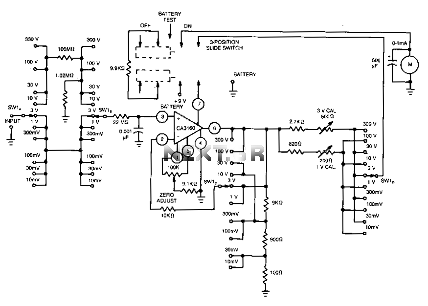
This voltmeter utilizes several beneficial characteristics of the CA3160 BiMOS operational amplifier. It offers voltage measurement capabilities ranging from 10 mV to 300 V. The circuit is powered by a single 8.4-V mercury battery and, at zero input, consumes...
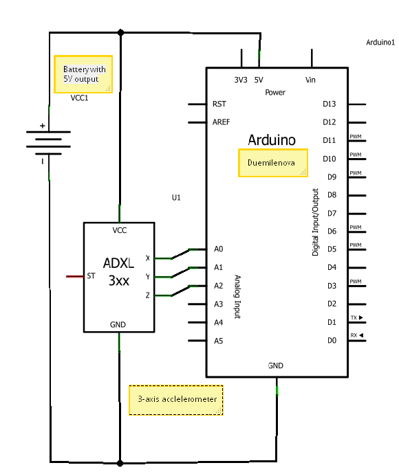
A circuit diagram illustrating the connection of an accelerometer to an Arduino board and an external power source. The circuit diagram depicts the integration of an accelerometer with an Arduino microcontroller, providing a clear representation of how these components interact...
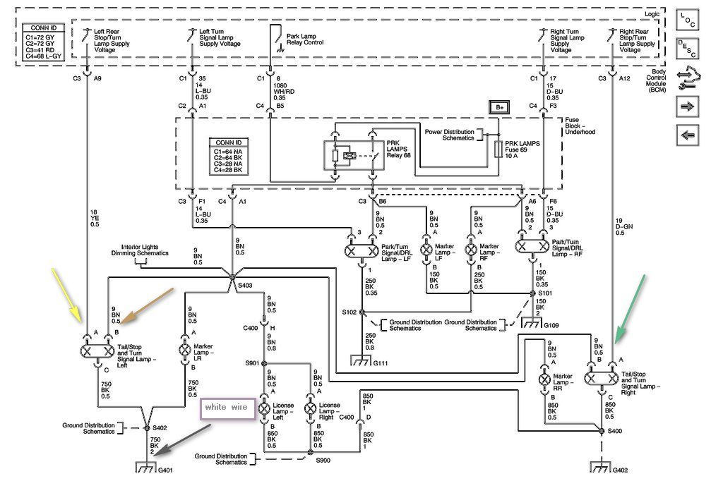
The left side of the vehicle operates correctly, with the running lights and brake light functioning properly. However, the turn signal is not working when wired directly into the harness. There is a preference to avoid purchasing a plug-in...
Warning: include(partials/cookie-banner.php): Failed to open stream: Permission denied in /var/www/html/nextgr/view-circuit.php on line 713
Warning: include(): Failed opening 'partials/cookie-banner.php' for inclusion (include_path='.:/usr/share/php') in /var/www/html/nextgr/view-circuit.php on line 713