
Bedwetting (Enuresis) Alarm with 555 timer
This project utilizes two LMC555 timer ICs configured to create a two-tone alarm system, suitable for alerting a sleeper when water is detected. The LMC555 timer is a versatile CMOS device that can be configured in astable mode to generate square wave outputs. The circuit operates on a 9V power supply, typically sourced from a standard transistor radio battery, ensuring portability and ease of use.
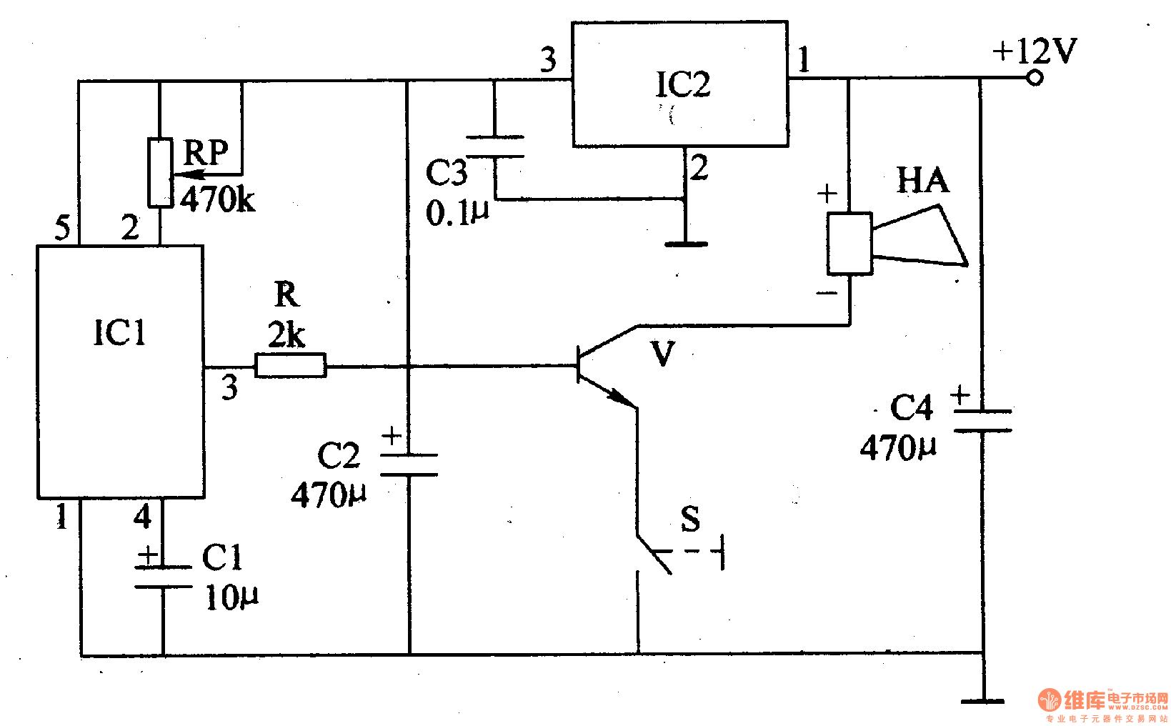
The first LMC555 (designated U2) is configured to produce a frequency of approximately 2.5 kHz, which is achieved by selecting a 100 kΩ resistor and a capacitor value of approximately 0.0027 µF, calculated based on the formula F = 1/(1.4 R C). The output from U2 drives a complementary pair of transistors (2N2222 and 2N2907), which function as emitter followers to effectively drive an 8-ohm speaker. This configuration is essential due to the high current demands of the speaker, which can peak at several hundred milliamps, far exceeding the output capabilities of the LMC555.
A volume control is integrated into the circuit between the output of U2 and the bases of the output transistors. The selected potentiometer value is 10 kΩ, which, while higher than the ideal resistance calculated based on load impedance and transistor beta, is functional for this application. The design allows for user-adjustable volume, accommodating varying preferences for alarm loudness.
To prevent habituation to the alarm tone, a second LMC555 (designated U1) is incorporated to introduce frequency modulation. This oscillator operates at approximately 3 Hz, modulating the frequency output of U2 through a 220 kΩ resistor connected to pin 5 of the LMC555. The modulation results in alternating high and low tones that help ensure the alarm remains effective in waking a deep sleeper.
The alarm circuit is designed to remain powered whenever the battery is connected, with reset inputs for both LMC555 ICs held low by a 1 MΩ resistor. This configuration ensures that the oscillators remain inactive until the water contacts are bridged, which is achieved when the resistance across the contacts drops below approximately 8 MΩ. Protective diodes (1N916) are placed across the contacts to safeguard the reset inputs from potential electrostatic discharges, while a 0.033 µF capacitor filters out stray electrical noise.
In idle mode, the circuit draws a minimal current of about 250 µA, allowing it to function for extended periods without battery replacement. When the alarm is activated, the average current draw increases to approximately 35 mA, which is well within the discharge capabilities of the chosen 9V battery, ensuring reliable operation.A simple two tone water alarm that is light enough to be worn on the upper arm of a sleeper is described. It uses two LMC555 CMOS timer chips followed by a complimentary pair of emitter followers to drive an 8 ohm speaker.
Power is supplied by a 9 volt transistor radio battery. An modification to produce a siren rather than two tone operation is discussed. A little experimentation with a signal generator showed that it would be very loud when driven with only 3 or 4 volts between 800 Hz and 3 kHz. I thought about ways to drive the speaker: use an LM324 quad op-amp followed by a pair of transistors, make a transistor multivibrator and have that drive a transistor buffer, make a couple of oscillators with a hex inverter.
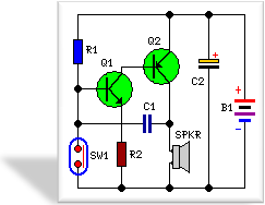
Just about the, the UPS delivery truck pulled up and I took delivery of a package from Mouser Electronics, which included among its contents, some LMC555N timer chips that I had ordered in anticipation of a very different project. This was the solution. The LMC555's can be set up to oscillate with a 50% duty cycle with only a single resistor and capacitor -a improvement over the recommended circuit for the old bipolar NE555, it can operate directly from a 9 volt transistor radio battery, and can be frequency modulated by injecting a signal into the control input (pin 5). The circuit shown in Figure 1 is the one that that fell into place. According to the data sheet, U2's oscillation frequency, F can be found by: F = 1/(1.4 R C) I wanted to run around 2.5 kHz, and chose a 100k resistor, and found the ideal value of the capacitor (from the formula above): C = 1/(1.4 R F) = 1/(1.4 x 100K 2500 Hz) = .0028 uf.
So, I used the closest standard value I had on had, which is .0027 uf. The output of the oscillator drives the complimentary pair made of the 2N2222 and 2N2907. The complimentary pair is necessary because the peak current into the speaker can reach several hundred milliamps, and the LMC555 cannot drive it directly. This pair has a tremendous amount of crossover distortion, so it would not be useful as shown here for normal audio use, but in this circuit, it is being driven by a square wave, and that distortion should not have any effect on the signal, other than to reduce the amplitude a little bit.
A volume control was inserted between the output of the LMC555N (pin 3) and the bases of the output buffer transistors, because the speaker is pretty loud and I wanted to give the user the option of turning it down if desired. This volume control has a fairly high resistance compared to the input resistance of the emitter followers, but I have a lot of 10k pots and it is sufficient in this application.
If the volume drifts a bit because of transistor gain drift, that's ok. It will still work fine. As a rule of thumb, for this sort of volume control, I would use a pot with a value of less than Zload X Beta, where Zload is the impedance of the load connected to the emitters and Beta is the current gain of the transistor expected at the load current. Based on this, the volume control's maximum resistance should have been about 500 Ohms (Beta of 50 or more x 10 Ohm load), Given that the highest resistance on the wiper is when it is in the center, a 500 Ohm maximum output resistance would be obtained with a 1k pot.
But, as I said I have a bag of 10k pots, so that's what I used. The constant tone U2 makes may not be enough to wake up a deep sleeper. If the user did not awaken enough when the alarm first went off, he could become used to the tone, even though it is loud, and go back to sleep. To make it harder of the user to go back to sleep, I added a second oscillator, U1, which runs at about 3 Hz, drives the frequency modulation input of U2 (pin 5) thorough a 220k resistor.
I selected 220k because it seemed appropriately large compared to the string of 100k resistors inside the LMC555, and when I tried it, it sounded just fine. The result is that when the circuit is on, the speaker is driven by alternating high and low tones above and below 2500 Hz.
I measured the rate of change, as set by U1, to be 3.3 Hz, by listening to it for 10 seconds and counting 33 changes in frequency. The circuit has the power applied whenever the battery is installed. The reset inputs (pin 4) to the LMC555 chips are held low (in the reset state) by the 1 Meg resistor from the reset inputs to ground.
This means that the oscillators aren't oscillating in the normal state. When the contacts become wet, they conduct. I figured a resistance of about 8 Meg or less would cause the chips to come out of reset. A quick check using some fixed resistors showed that this one triggered when 4.7 Megs was placed across the contacts - plenty sensitive, and maybe too sensitive for some cases. If you want to lower the sensitivity, reduce the value of the 1 Meg resistor. A pair of 1N916 diodes keeps the voltage across the "Contacts" input, such as might be caused by electrostatic discharge, from causing damage to the reset input of the LMC555's by shunting most of the current to ground or the battery.
A 0.033 uf capacitor across the "Contacts" input keeps the circuit from responding to stray electrostatic fields such as may be encountered near an electric blanket. When the circuit is idling -that is not sounding the alarm, the circuit only draws about 250 microamps, so it can idle for a long time, probably months at a time, so there is no on-off switch.
I meaured the average current from the battery at about 35 milliamps when the alarm was sounding, which is well within the capabilities of the 9 volt transistor radio battery. 🔗 External reference
Related Circuits
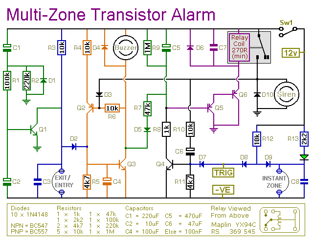
This is a simple transistor-based burglar alarm circuit. Its features include automatic exit and entry delays, along with a timed bell cut-off and reset. It is designed to be used with common types of normally-closed input devices such as...
3V battery-powered circuit that emits a beep after a fixed delay of several minutes. This circuit was created in response to requests from users seeking a timer functionality. The described circuit operates on a 3V power supply, making it suitable...
This circuit, housed in a compact plastic enclosure, is designed for portability and can easily fit into a bag or handbag. A small magnet is positioned near a reed switch and is attached to the individual carrying the bag...
The following circuit illustrates a low voltage power supply (PSU) for Nixie tubes utilizing a 555 Timer integrated circuit (IC). The coil used in this schematic is purchased from a store. The described circuit operates as a low voltage power...
The motorcycle anti-theft alarm described in this article utilizes a proprietary displacement sensor. It is characterized by high sensitivity, good reliability, a low false alarm rate, and ease of construction. The principle of the circuit involves an integrated vibration...
At the core of this circuit is a precision integrated temperature sensor, the LM35 (IC1), which provides a linear and directly proportional output related to temperature measurements. The LM35 temperature sensor is a well-known device used for temperature sensing applications....
Warning: include(partials/cookie-banner.php): Failed to open stream: Permission denied in /var/www/html/nextgr/view-circuit.php on line 713
Warning: include(): Failed opening 'partials/cookie-banner.php' for inclusion (include_path='.:/usr/share/php') in /var/www/html/nextgr/view-circuit.php on line 713