
BFO Circuit
The described circuit serves as a highly stable beat frequency oscillator (BFO) designed to minimize drift, ensuring that the BFO frequency remains consistent regardless of power cycling or temperature variations. The core component is the Murata CSB 455E resonator, which operates within a frequency range of 430-509 kHz, specifically optimized for applications between 452.6 kHz and 455.0 kHz. This frequency range is particularly suitable for the intended receiver application.
The circuit includes a 455 kHz intermediate frequency (IF) transformer, designated as T1, which can be omitted if not available. The presence of this transformer is beneficial as it aids in reducing harmonic distortion from the oscillator, thereby improving the overall signal quality.
The circuit utilizes a field-effect transistor (FET) for amplification, with flexibility in component choice. Common alternatives to the MPF102 include the 2N5486 and 2N4416 FETs, which can be used interchangeably based on availability and performance characteristics. The design emphasizes a conservative drive level to the product detector to prevent excessive leakage into the IF strip, which can lead to unintended oscillations. Such oscillations may manifest as erratic behavior in received continuous wave (CW) signals, signaling a need for adjustment in the BFO drive level.
The circuit's design is inspired by literature that explores the application of ceramic resonators in variable frequency oscillators (VFOs), highlighting the potential for covering a wide frequency range effectively. The referenced articles provide further insights into optimizing resonator usage for various frequency applications, underscoring the versatility and efficacy of resonator-based circuits in RF design.This circuit was used to stop all the BFO drift. The circuit is extremely stable. Turn the receiver off, and then on at any time and temperature, the BFO frequency is exactly the same. The resonator is a Murata CSB 455E. Murata's series number is CSBLA_E 430-509kHz. The data sheet is a .pdf file and the information on this resonator starts on page 28, "Ceramic Resonators(CERALOCK) Lead Type Two-Terminal CSBLA Series".
The last time I checked I didn't find it on the site, but that doesn't mean you can't find it. T1 is a 455kHz IF transformer and may be eliminated if one is not available. This was a circuit I had lying around and had the transformer already wired in the output. It does help to eliminate harmonics from the oscillator. The FET can be any part number. Some common ones other than the MPF102 are the 2N5486 or 2N4416. The application above covers 452.6 to 455.0 kHz. This is the perfect range for the receiver. The circuit above could be improved to expand the range, but an extended range was not necessary. The amount of drive delivered to the product detector should be on the low side. Driving the product detector too hard will cause leakage to the IF strip and cause oscillations. If you are listening to a CW signal that suddenly jumps around, oscillations in the IF strip from too much BFO drive should be investigated. No problems were experienced with the Resonator/amplifier shown above, but the Hartley (below) with a MOSFET amplifier had to be tamed down.
This circuit was inspired by the article "Ceramic Resonators for Cheap and Cheerful VFOs", by Jack Ponton, GM0RWU. Also check out "Mixer VFOs for the HF bands." This article was quite an eye-opener that showed a huge range could be covered by resonators.
He shows a circuit that covered 13.990 to 14.280 MHz. The article is well worth reading. 🔗 External reference
Related Circuits
The apparatus consists of a cavers point detection circuit and a triggering display circuit. The cavers instrument functions as a test probe, which, when held in one hand, can detect acupuncture points by touching the skin with another probe....
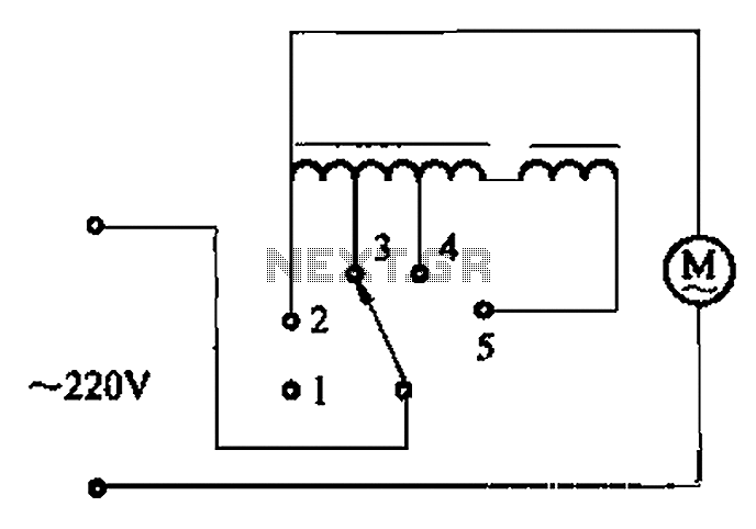
The circuit illustrated in Figure 3-2 features a loop reactor governor that incorporates a series reactor. The reactor can be constructed using a TV choke and is designed to be approximately 3mm in height. It utilizes a strength wire...

The circuit illustrated is designed to generate up to 5 watts of RF output in the 40-meter (7 MHz) amateur band. The coils depicted are wound on toroidal cores from Armdon Associates Inc., with part numbers provided in the...
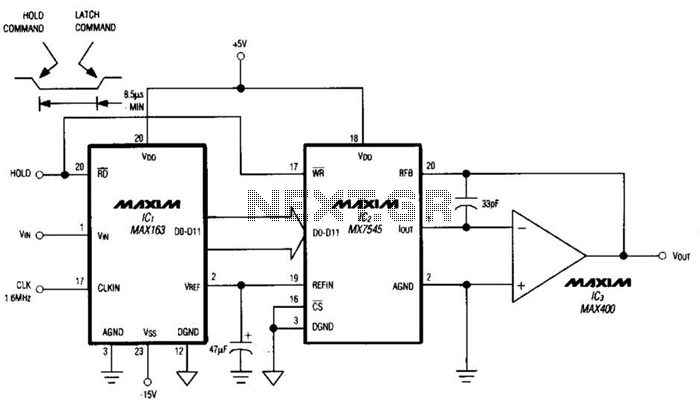
Driving a D/A converter using an A/D converter provides an overall analog-hold function. Although this function has limitations in output resolution, it offers zero voltage droop and infinite hold time. The A/D converter depicted (IC1) features a 12-bit compatible...
This circuit can be used to operate an electric strike or an electromagnetic lock on a door. It is not the door being opened/closed, but a small electromagnetic strike which unlocks the door. The opener has the following features...
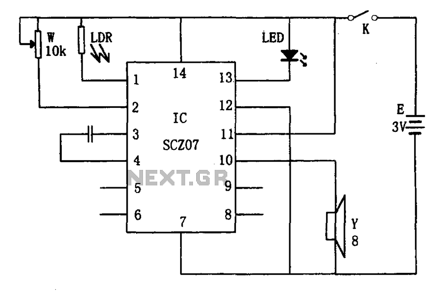
The weak light alarm circuit is illustrated in the figure. The oscillator circuit's core component is the SCZ07. The input signal is controlled by a potentiometer (W) and the output signal is processed by a photoresistor (LDR). The circuit...
Warning: include(partials/cookie-banner.php): Failed to open stream: Permission denied in /var/www/html/nextgr/view-circuit.php on line 713
Warning: include(): Failed opening 'partials/cookie-banner.php' for inclusion (include_path='.:/usr/share/php') in /var/www/html/nextgr/view-circuit.php on line 713