
Bias Supply For Microwave Preamps
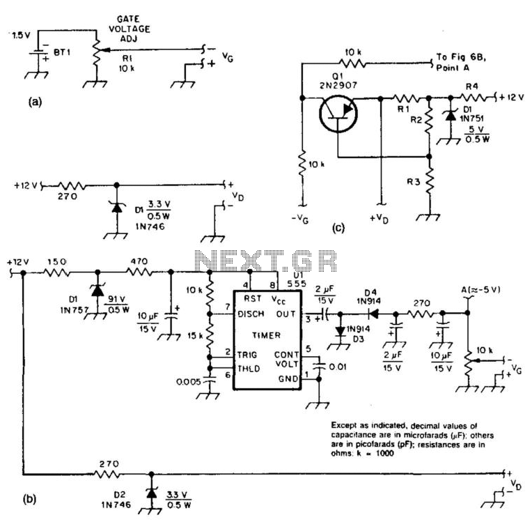
The circuits described are essential for ensuring proper biasing of microwave preamplifiers, which are crucial in high-frequency applications. The passive supply in Figure 51-5(a) typically consists of resistors and capacitors that provide a stable voltage to the preamp. This method is straightforward and cost-effective, but it may not offer the precision required in high-performance applications.
In contrast, the active supplies illustrated in Figures 51-5(b) and 51-5(c) employ more complex circuitry to achieve better regulation of the supply voltages. The component Ul is responsible for generating a negative voltage supply, which is often necessary for the operation of certain types of microwave preamps that require a negative bias. The use of an active component allows for improved voltage stability over varying load conditions compared to a passive supply.
Moreover, the transistor Ql plays a crucial role in these active circuits by controlling the drain voltage and current. This configuration allows the circuit to maintain consistent performance regardless of variations in the GASFET characteristics, such as threshold voltage and transconductance. By isolating the biasing conditions from the GASFET's inherent properties, the design enhances the overall reliability and performance of the microwave preamplifier.
In summary, the combination of passive and active biasing circuits provides flexibility in designing microwave preamp systems, allowing engineers to select the most appropriate method based on performance requirements and application constraints. These two circuits provide bias for the microwave preamps shown in this text. The circuit in Fig. 51-5(a) is a simple passive supply. Figures 51-5(b) and 51-5(c) are active supplies, with Ul generating a negative supply and Ql setting the drain voltage and current, independent of GASFET characteristics. 🔗 External reference
Related Circuits
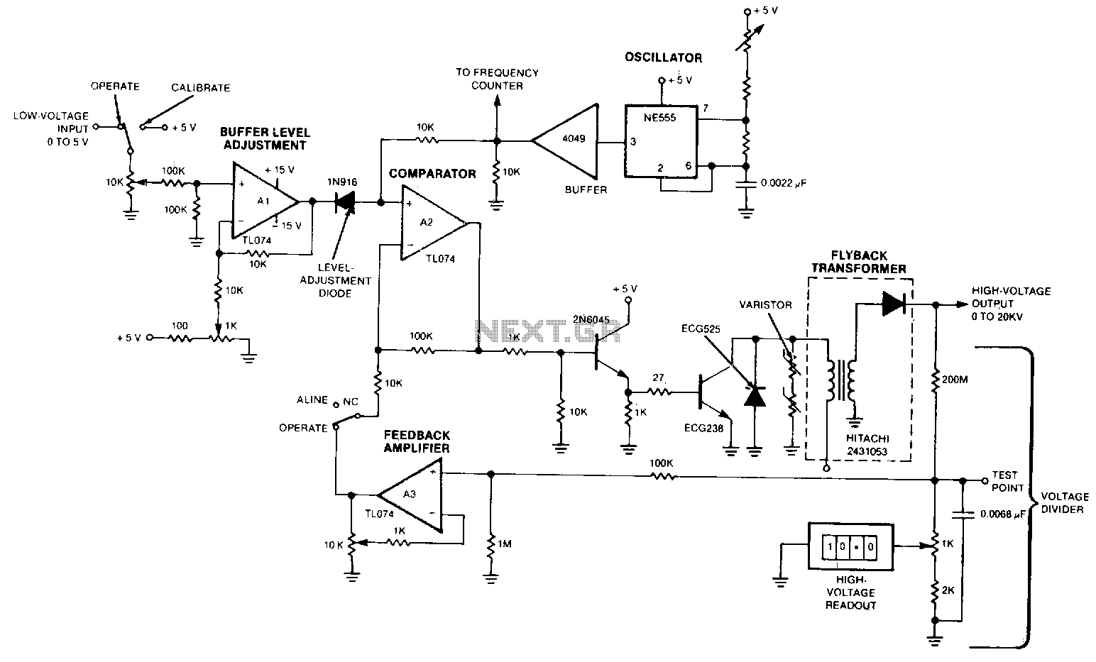
The output voltage varies approximately linearly up to 20 kV as the input voltage is adjusted from 0 to 5 V. A 5-0 potentiometer is used to tune the oscillator, optimizing the output voltage at the frequency of maximum...
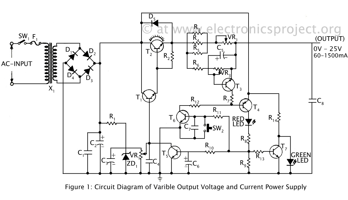
A ripple-free, short-circuit protected variable output voltage and current power supply is presented on this website as a verified project. The circuit diagram includes a description of various power supply circuits. This power supply circuit is designed to provide a...
For its maximum result, the final stage of the amplifier should have the proper power supply, as the flowing currents are very high. A Class A amplifier requires attention. These are the rules for the power supply for the...
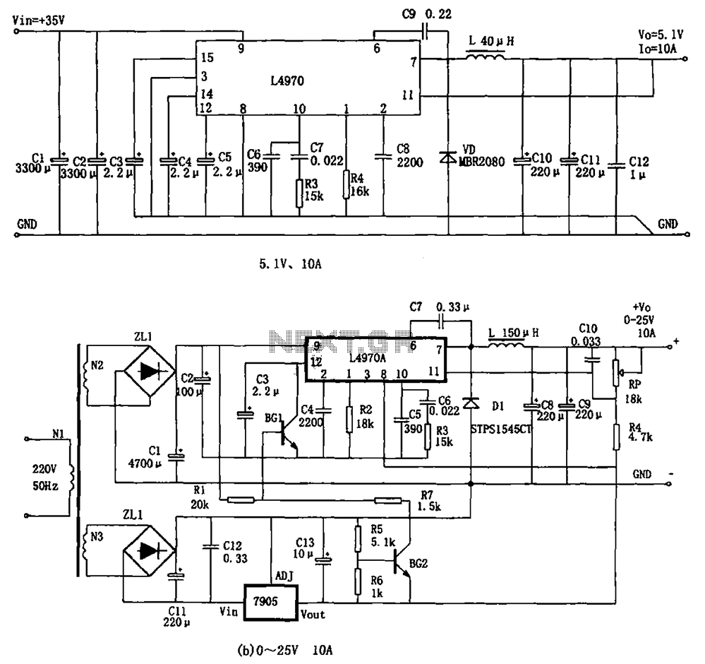
The L4970A power switching supply is a high-power monolithic integrated switching regulator, packaged in a SIP-15 format. It has specific characteristics: (1) The input voltage must be at least 11V, typically ranging from 15V to 40V; (2) The output...
The 555 is wired as an astable and the capacitor is charged only through the 4.7Kohm trimmer (notice the diode) and discharged only through the 2.2 Kohm trimmer, making the duty cycle fully adjustable. The square wave is then...
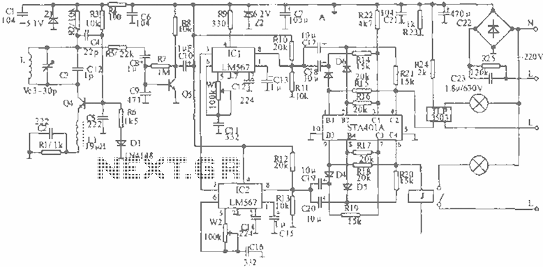
When the infrared receiver tube PH302 receives a signal from the remote control, the CX20106A selected frequency amplifier outputs a low-frequency signal. The low-level signal charges capacitor C through diodes D and R, causing the negative side potential of...