Binary Coded Decimal
1. Definition of Binary Coded Decimal
1.1 Definition of Binary Coded Decimal
Binary Coded Decimal (BCD) is a method of encoding decimal numbers in a binary format. Each digit of a decimal number is represented individually as a four-bit binary sequence. This representation is particularly relevant in systems that interface directly with decimal display systems or device inputs, such as digital clocks and calculators, where human readability is paramount.
In a BCD representation, the decimal digits 0 through 9 are mapped to their corresponding four-bit binary equivalents:
- Decimal 0: 0000
- Decimal 1: 0001
- Decimal 2: 0010
- Decimal 3: 0011
- Decimal 4: 0100
- Decimal 5: 0101
- Decimal 6: 0110
- Decimal 7: 0111
- Decimal 8: 1000
- Decimal 9: 1001
For instance, the decimal number 45 is represented in BCD as a combination of its digits (4 and 5), encoded as:
This means the digit '4' is stored as 0100 and '5' as 0101. Thus, BCD encodes decimal numbers in a straightforward manner that allows for simple conversion between binary and decimal without requiring complex arithmetic operations.
The practical applications of BCD encoding excel primarily in digital electronics, where the need for decimal representation is integral. Devices such as digital voltmeters, scoreboards, and other systems requiring precision in decimal representation take full advantage of BCD encoding. In computer engineering, BCD is less commonly used compared to pure binary systems; however, it remains indispensable in specific contexts where human interface is a critical aspect.
Moreover, BCD presents a distinct advantage in terms of ease of display and low computational overhead when converting back to decimal, contrasted with standard binary representation which can introduce processing complexity. This makes BCD a preferred choice for certain types of applications, particularly in user-centric devices.
In summary, while Binary Coded Decimal may appear straightforward, its relevance in practical applications illustrates the intersection of human factors with digital electronics. Understanding BCD provides a foundation for more complex encoding systems and digital design methodologies that engineers will encounter in their work.
1.2 Historical Context and Development
The Binary Coded Decimal (BCD), a form of number representation, has its roots deeply embedded in the evolution of numerical systems and computing devices. To fully appreciate its significance, we must first examine the context of its development, which intersects various domains of mathematics, engineering, and early computer science.
The concept of binary representation dates back to ancient civilizations, but it gained traction in the 20th century due to advancements in electronic computing. Binary systems, characterized by the use of only two digits — 0 and 1 — became foundational in the design and construction of digital circuits. However, as computers transitioned from mere computation devices to tools that interfaced with human users, the need for a more intuitive way to represent decimal numbers emerged.
In the early 1950s, the advent of electronic computers highlighted the inadequacies of directly handling decimal numbers in their binary form. Traditional binary representation became cumbersome for applications requiring a frequent human interface, such as banking and accounting systems — both domains where precision in decimal representation is critical. It was within this landscape that BCD was conceived.
BCD effectively bridges the gap between human-readable decimal and machine-readable binary by encoding each digit of a decimal number within its own separate binary 4-bit representation. For example, the decimal number 25 would be represented in BCD as 0010 0101, where 0010 corresponds to 2 and 0101 corresponds to 5. This separateness allows for simpler conversion and error-checking mechanisms in computer systems.
Where \( D_i \) is the decimal digit, and \( b_3, b_2, b_1, b_0 \) represent its corresponding bits in BCD. This formation simplifies processing, especially in financial computing, where rounding errors can lead to significant discrepancies.
Throughout the 1960s, BCD found widespread application in calculators and digital displays, enhancing user interactions. The standardization of BCD was propelled by organizations such as the American National Standards Institute (ANSI), which recognized the importance of maintaining data consistency across various systems. As microprocessors emerged in the late 20th century, BCD further established itself, particularly in embedded systems where compact code and arithmetic operations were vital.
One notable practical relevance of BCD is its utility in digital clocks and measuring instruments, where it aids in straightforward human interpretation of data. Unlike pure binary, BCD allows users to read values quickly, facilitating efficiency in environments where time is of the essence. This capacity for clarity has made it an enduring method of encoding decimal numbers, even in contemporary applications where binary predominates.
As we continue to explore BCD in forthcoming sections, we will delve into its mathematical properties, implementations, and comparisons with other number systems, providing a comprehensive view of its standing in today's technological landscape.
1.3 Importance in Digital Electronics
The Binary Coded Decimal (BCD) representation plays a crucial role in the realm of digital electronics, particularly when precise numerical representation and human readability are paramount. Unlike pure binary systems, which can lead to complexities in human interaction with digital devices, BCD serves as a bridge between the digital and analog worlds.
To appreciate the importance of BCD, it is essential to understand its structure. Each decimal digit is represented using four bits, allowing for binary combinations that correspond directly and unambiguously to their decimal equivalents. This compact yet effective representation mitigates common conversion errors that occur when dealing with binary values in human-centric applications, such as calculators, digital clocks, and measuring instruments.
Real-World Applications
In practical settings, BCD is not merely a theoretical concept; it has significant implications in various applications:
- Digital Clocks: Most digital clocks utilize BCD to enable easy readability of time, where each digit may be displayed separately.
- Calculators: BCD ensures quick conversion between user inputs and internal binary processing, enhancing calculation speed and accuracy.
- Frequency Counters: Many digital frequency counters adopt BCD to present frequency measurements in a human-readable format, streamlining analysis.
Considering these applications reveals BCD’s indispensable nature in electronics. The ease of transition from BCD to decimal makes it particularly favorable for interfaces that require frequent human interaction. For example, when you're inputting a numerical value in an electronic device, the use of BCD ensures that you see the decimal-value representation directly corresponding to your input, without the errors that might compromise data integrity in pure binary systems.
Precision and Efficiency
Moreover, the efficiency of BCD is evident when performing arithmetic operations. While addition and subtraction in decimal can be efficiently managed, binary addition often requires additional handling to ensure carry operations are correctly facilitated. With BCD, however, the implementation of a simple correction mechanism simplifies the process, ensuring results stay within the bounds of 0-9 for any single digit. The downsides of BCD in terms of severe multiplication and division overheads cannot be understated, yet in applications where decimal precision is paramount, BCD operates smoothly within its confines.
The evolution of BCD usage in devices can be traced back to early computing systems where digital circuits needed to communicate effectively with human users. This historical context highlights the ongoing relevance of BCD in today's high-speed computing environments where legacy systems occasionally intermingle with modern architectures.
As a final thought, it's evident that BCD is not just an abstract notion; its real-world importance is reflected in its capacity to enhance usability, efficiency, and accuracy in a variety of digital electronics environments. Recognizing these factors empowers engineers and researchers to make informed design choices when developing systems that require an interface between human cognition and electronic processes.
2. How BCD Represents Decimal Numbers
2.1 How BCD Represents Decimal Numbers
Binary Coded Decimal (BCD) is a method used to represent decimal numbers in binary form, where each digit of a decimal number is represented individually by a fixed number of binary bits. This method is particularly useful in applications where the decimal representation is vital, such as in digital clocks and calculators, where human readability is essential.
Understanding BCD Representation
In BCD, each decimal digit from 0 to 9 is encoded using a group of four binary bits. The encoding scheme is simple: the decimal digit is converted to its binary equivalent. For instance:
- Decimal 0 is represented as 0000
- Decimal 1 as 0001
- Decimal 2 as 0010
- Decimal 3 as 0011
- Decimal 4 as 0100
- Decimal 5 as 0101
- Decimal 6 as 0110
- Decimal 7 as 0111
- Decimal 8 as 1000
- Decimal 9 as 1001
As depicted, each decimal digit is represented by a unique 4-bit binary sequence, which allows the representation of decimal numbers in a format that is easier to interpret in digital systems, especially those that interact with humans.
Here, b denotes the bits representing the decimal number. For example, the decimal number 47 can be represented in BCD as follows:
- 4 is represented as 0100
- 7 is represented as 0111
Thus, the BCD representation of 47 is 0100 0111.
Limitations and Advantages of BCD
While BCD provides a straightforward method for encoding decimal numbers, it has its limitations. The primary disadvantage is that it is less space-efficient than pure binary representation. For instance, representing the decimal number 99 in binary is 1100011, consuming only 7 bits. In contrast, its BCD representation is 1001 1001, using 8 bits. This increases storage and transmission requirements.
Despite these limitations, BCD's primary advantage is its direct correlation to human-readable decimal formats, making it ideal for applications like digital clocks or calculators, where the output must be easily understood by users.
Applications in Real-World Systems
BCD finds its utility in several real-world applications such as:
- Digital meters: In voltmeters and ammeters, BCD allows for direct representation of the measurements.
- Calculators: BCD helps store numbers in a format that can be easily manipulated for arithmetic operations where decimal accuracy is critical.
- Clocks and timers: The readability of time representation in BCD fosters user interaction without conversion complexity.
Overall, BCD serves as a bridge between the binary processing capabilities of machines and the decimal format that humans use every day, making it a fundamental concept in digital electronics.
2.2 Comparison with Binary Numbering System
The Binary Coded Decimal (BCD) system and the traditional binary numbering system both serve essential functions in digital electronics and computing, yet their underlying principles and applications differ significantly.
While binary employs a base-2 system utilizing only two digits, 0 and 1, BCD represents each decimal digit with its own binary sequence. In essence, it encapsulates decimal digits (0-9) using four bits, which can be translated in various ways—typically using a weight system that directly corresponds to the decimal values. This divergence in representation leads to unique advantages and limitations in both systems.
Encoding Comparison
When comparing how numbers are represented in both systems, consider the decimal number 27:
- In binary, 27 is represented as:
- In BCD, 27 is represented as two separate 4-bit sequences:
As illustrated, the binary form condenses the number into a single sequence of bits, whereas BCD expands each decimal digit into four bits. This expansion leads to various implications.
Performance Analysis and Practical Impacts
The choice between BCD and binary can have notable consequences in computing systems:
- Efficiency in Calculation: Binary computations are typically faster and require less space compared to BCD. This efficiency is crucial in applications like microprocessors and digital signal processors where processing speed is paramount.
- Human Readability: BCD presents a clear advantage when dealing with human interface applications, where presenting decimal values is more intuitive (e.g., calculators and digital watches).
- Complexity in Conversions: Converting between binary and BCD can introduce additional steps. Binary systems can represent the entire number system more holistically and natively in computer architectures.
Furthermore, it is important to consider computational overhead when deciding on a numbering system. BCD could require additional circuitry and processing time to convert and manipulate, especially evident in older calculators or embedded systems tasked with decimal calculations.
Real-World Examples
In practice, the choice of BCD or binary impacts various technologies:
- Electronic Voting Machines: These often prefer BCD for displaying choices, converting input signals to decimal values for easy human interpretation.
- Digital Clocks: Many digital clocks use BCD for representing time effectively while ensuring ease of user interaction.
In conclusion, understanding the trade-offs and applications of BCD versus binary is crucial for design decisions in electronics and computing. The systems are not interchangeable; rather, they complement each other, each suited to specific tasks.
2.3 BCD Graphed Representation
The Binary Coded Decimal (BCD) system serves as a convenient way to represent decimal numbers in binary form. While its implementation in digital circuits is significant, understanding its graphed representation opens up a visual comprehension of numerical transitions, arithmetic operations, and encompassing behaviors.Understanding BCD Representation
To appreciate the graphed representation of BCD, we first acknowledge that in BCD, each digit of a decimal number is represented by its equivalent binary value using four bits. For instance, the decimal number 25 would be represented in BCD as: - 2 → 0010 - 5 → 0101 By plotting the individual components of the BCD representation, one can create a graph where the x-axis denotes the decimal digits and the y-axis indicates their respective binary representation.Graphical Representation of BCD
When graphing BCD values, one can visualize transformations from decimal to binary. Each digit's conversion from its decimal form into a binary representation can be expressed as follows: 1. Each decimal digit is taken from 0–9 and converted into its 4-bit binary equivalent. 2. Using Cartesian coordinates, each point on the graph aligns the decimal digit against its binary equivalent. The resulting graph can be portrayed as a series of discrete jumps, illustrating how BCD delineates the range of binary representations available for decimal digits. For example, to graph the BCD representation for decimal digits 0 to 9, the following coordinates can be plotted: - (0, 0000), (1, 0001), (2, 0010), (3, 0011), (4, 0100), - (5, 0101), (6, 0110), (7, 0111), (8, 1000), (9, 1001). Each point corresponds to a switch in binary state, allowing engineers and researchers to visualize and analyze how binary transitions occur distinctly for BCD across the range of decimal digits.Practical Applications and Significance
Visualizing BCD through a graph enhances the understanding of its application in digital electronics, particularly in devices like digital clocks, calculators, and measurement systems where clarity and precision of numerical representation are essential. Such graphics are also beneficial during the debugging process in digital systems, as they allow engineers to quickly identify discrepancies between expected and actual outputs. In computational systems, BCD provides the functionality needed for clear decimal arithmetic, yet its graph representation also reveals potential pitfalls—especially during arithmetic operations, where carrying between digits can introduce additional complexity. The combination of rigorous numerical representation and intuitive graphical interpretation enables a deeper grasp of BCD’s operational framework, facilitating a better grasp of real-world applications across various electronic systems and algorithms.Conclusion
Through the graphed representation of BCD, we uncover a visual understanding of binary encoding that not only serves theoretical insight but also drives practical applications in digital systems. This bidirectional approach—linking number theory with graphical interpretations—enhances computational methodologies and system reliability.3. Use in Digital Displays
3.1 Use in Digital Displays
The use of Binary Coded Decimal (BCD) in digital displays is significant in modern electronics, especially within devices that require numerical output, such as calculators, digital clocks, and various measuring instruments. By representing each digit with a fixed 4-bit binary number, BCD allows straightforward mapping of decimal numbers to digital displays, ensuring both accuracy and ease of interpretation for end users.
Each decimal digit from 0 to 9 corresponds to its unique four-bit binary representation, which simplifies the process of converting binary data to human-readable format. This capability is crucial because it reduces potential errors that might occur during conversion from binary to decimal and vice versa, especially in applications requiring precise numerical readouts.
How BCD Works in Digital Displays
In BCD, each digit of a decimal number is coded separately in binary, leading to an efficient representation within digital circuits. For example, to represent the decimal number 25 in BCD, we break it down into its constituent decimal digits:
- 2 is represented as 0010
- 5 is represented as 0101
The combination yields a BCD representation of:
This individual coding allows BCD to drive 7-segment displays effectively. In a 7-segment display, each of the segments (labeled A through G) can be activated by a combination of inputs corresponding to the BCD representation of the digit to be displayed.
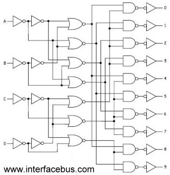
Example of BCD to 7-Segment Decoder
Consider a BCD to 7-segment decoder such as the 74LS47. The decoder converts the BCD input into signals that control the segments of the display. Here is how the binary inputs relate to the outputs controlling the segments:
- Inputs (0000 - 0009) are valid BCD inputs, while (1010 - 1111) are invalid.
- The corresponding logic output activates the segments required to display digits 0 through 9.
A truth table can be created to detail how each BCD input corresponds to the segments lit up in a 7-segment display. The segments are labeled as follows:
- A (top)
- B (upper right)
- C (lower right)
- D (bottom)
- E (lower left)
- F (upper left)
- G (middle)
As an illustration, the BCD input for '2' (0010) activates segments A, B, C, E, and D, effectively rendering the numeral '2' on the display.
Real-World Applications
BCD is not just theoretical; its applications are pervasive in everyday technology:
- Digital Clocks: BCD displays are used extensively in digital clocks, allowing for intuitive and straightforward readouts of hours and minutes.
- Calibrated Readouts: Measuring and instrumentation equipment, such as voltmeters and ammeters, frequently utilize BCD to represent readings more accurately.
- Calculators: BCD representation in calculators ensures that calculations involving decimal fractions maintain precision without overflow errors that might arise if decimal points were derived from pure binary representations.
Overall, BCD's role in digital displays resonates with its efficiency and the straightforwardness with which it bridges the gap between binary systems and human-readable formats. This symbiosis between digital technology and user interface is essential in creating devices that are not only functional but also user-friendly.
3.2 Implementation in Calculators
The implementation of Binary Coded Decimal (BCD) in calculators marks a pivotal advancement in digital electronics, streamlining numerical data representation and manipulation. BCD enables numbers to be represented in a format that maintains a direct correspondence to human-readable decimal digits, allowing for simplified calculation processes while minimizing conversion errors commonly seen in pure binary representations. This section delves into the architecture and operational mechanisms through which calculators utilize BCD for efficient number processing.
Understanding BCD Representation
In BCD, each decimal digit is represented by its four-bit binary equivalent. For instance:
- 0 is represented as 0000
- 1 is represented as 0001
- 2 is represented as 0010
- 3 is represented as 0011
- 4 is represented as 0100
- 5 is represented as 0101
- 6 is represented as 0110
- 7 is represented as 0111
- 8 is represented as 1000
- 9 is represented as 1001
This systematic encoding allows calculators to handle decimal digits more intuitively, directly converting user inputs into a format readily usable by the device's internal circuitry.
Microcontroller Implementation: A Case Study
Most modern calculators employ microcontrollers equipped with the capability to process BCD. These microcontrollers are programmed to convert user input from decimal to BCD and vice versa. A typical workflow involves:
- User input is captured via a keypad interface.
- Each keypress is converted from its decimal representation to BCD.
- Arithmetic operations are performed directly on the BCD values.
- Results are converted back to decimal representation before displaying the output.
This conversion process ensures greater accuracy during computation, reducing the need for decimal-to-binary conversions which can lead to miscalculations due to binary approximations.
The Arithmetic Operations in BCD
Calculators implement adders specifically designed for BCD arithmetic, such as the BCD adder. The BCD adder incorporates correction mechanisms to handle cases where outputs exceed BCD valid ranges, i.e., values above 1001 (9 in decimal).
For example, consider the addition of two BCD digits:
- When adding 0110 (6) and 0101 (5), the binary sum is 1011 (11 in decimal).
- This value goes beyond valid BCD representation, necessitating an adjustment. The calculator adds a correction value of 0010 (2) to the result, yielding:
- This results in 1101 (13) in BCD form, which is a valid representation of 13.
Practical Applications and Historical Context
Though calculators are a common application of BCD encoding, similar principles are utilized in various digital devices such as digital clocks and electronic measuring instruments. Historically, the adoption of BCD in these devices facilitated easier user interactions by aligning computational processes closer to human numerical systems, leading to increased reliability in output.
Modern calculators have evolved to include functions beyond mere arithmetic, utilizing BCD to efficiently perform operations involving floating-point numbers and complex mathematical functions while still maintaining user-friendly interactions.
In conclusion, the implementation of BCD in calculators exemplifies a crucial intersection of digital technology and user experience, resulting in devices that prioritize efficiency and accuracy. Consequently, understanding BCD's role further emphasizes the importance of effective data representation in the broader landscape of electronics.
3.3 BCD in Microcontrollers
Understanding BCD Representation
BCD encodes decimal digits using four bits, allowing it to represent each digit from 0 to 9 with their binary equivalents: - 0 in BCD as 0000 - 1 as 0001 - 2 as 0010 - Up to 9, which is encoded as 1001. The advantages of BCD over binary-coded integers become apparent when interfacing microcontrollers with displays. For example, a microcontroller using BCD can output values directly to a seven-segment display with minimal conversion, whereas a binary representation would require additional manipulation to convert from binary to decimal.Microcontroller Architectures Supporting BCD
Many common microcontrollers, including the popular 8051 and PIC series, have built-in support for BCD operations. For instance, the 8051 instruction set includes specific BCD arithmetic operations that simplify handling decimal numbers. In these architectures, there are dedicated instructions (e.g., DAA - Decimal Adjust after Addition) which help correct the BCD values post arithmetic operations, maintaining their validity.BCD Arithmetic in Microcontrollers
Implementing BCD operations involves distinct strategies: 1. Addition: When adding two BCD values, if the result exceeds 9, an adjustment of six (0110 in binary) is applied: - Suppose we add 7 (0111) and 5 (0101). - The binary sum would be 1100, which corresponds to 12. To adjust, we add 6: $$ 1100 + 0110 = 10110 \quad (\text{Discard the carry for correct BCD: } 0010) $$ Here, the output becomes 12 in BCD. 2. Subtraction: Similar adjustments are needed if the subtraction yields a negative result. Techniques can vary based on whether the microcontroller provides direct instruction support or requires manual algorithmic implementation.Practical Applications of BCD in Embedded Systems
The practicality of BCD in embedded systems is most noticeable in the domain of consumer electronics: - Digital Clocks: Facilitating easy display of hours and minutes by directly outputting BCD to a seven-segment display. - Digital Meters: Utilizing BCD for easy scaling and display of measurements, which enhances user experience. - Financial Systems: As BCD elegantly handles decimal arithmetic, it becomes indispensable for applications requiring currency representation. The integration of BCD allows for straightforward communication between the microcontroller and external interfaces. When a microcontroller sends BCD data to an LCD or a similar display, the decimal digits are represented without requiring additional conversion, reducing complexity and potential errors. To encapsulate the significance of BCD in microcontrollers, it allows for efficient data processing, minimal external interfacing complexities, and better human-computer interaction, making it an invaluable approach in modern electronics design.4. Advantages of Using BCD
4.1 Advantages of Using BCD
Binary Coded Decimal (BCD) presents several advantages, particularly in the context of its application in electronic and computational systems. This unique encoding method, which represents each digit of a decimal number using its binary equivalent, functions distinctly from pure binary representation. This section explores the practical benefits of using BCD in various fields, highlighting why it has remained a relevant choice in certain applications despite the advent of more advanced numerical systems.
Enhanced Readability and Simplicity in Processing
One of the primary advantages of BCD is its ability to maintain readability. While binary representation can introduce complications during the conversion and interpretation stages, BCD provides a straightforward correlation between binary values and decimal digits. For instance, the decimal number 45 can be directly represented in BCD as 0100 0101, where the first group corresponds to the digit 4 and the second group corresponds to the digit 5.
This numeric alignment fosters simplicity in applications, particularly in user interfaces and display systems where human interpretation is necessary. In areas such as digital clocks, financial calculations, and computing systems that frequently interface with users, BCD can enhance both usability and error reduction.
Efficient Conversion and Mathematical Operations
Another significant advantage of using BCD lies in its suitability for arithmetic operations. When performing calculations, particularly addition and subtraction, BCD can streamline processes by enabling direct addition of BCD values, as each 4-bit group is a complete decimal number. This feature reduces the number of steps needed to execute arithmetic operations, making BCD particularly attractive for applications such as calculators and digital systems where speed and efficiency are paramount.
The equation above describes the carry generated during addition in BCD, where A and B are the BCD operands, and C is the carry from the previous operation. Notably, if the sum exceeds 9 (1001) in decimal, an adjustment—specifically the addition of 6 (0110)—is applied to convert the sum back into valid BCD.
Support for Complex Numeric Systems
BCD provides vital support in domains requiring representation of large numerical values without risking precision loss. When a system handles extensive datasets or financial computations, maintaining accuracy is crucial. Systems utilizing BCD are less prone to errors stemming from rounding, especially within decimal systems. This accuracy is particularly beneficial in financial transactions and scientific computations where every digit counts.
Compatibility with Legacy Systems
Moreover, BCD retains an essential role in legacy systems that continue to operate based on older digital architectures. Ascribed a practical advantage in maintaining compatibility across technologies, BCD enables seamless interactions between newer devices and older infrastructures. Legacy systems still widely utilized in industries—such as banking, telecommunications, and transportation—demonstrate the lasting utility of BCD.
Ultimately, while BCD may not be the most efficient method for all numerical applications, its advantages make it indispensable in specific scenarios, proving that the right choice of encoding can profoundly impact functionality and user experience.
4.2 Disadvantages and Limitations
When utilizing Binary Coded Decimal (BCD), it’s critical to evaluate its inherent disadvantages and limitations that can impact its application in various engineering and computing contexts. Although BCD provides a straightforward decimal representation, especially useful in digital displays and certain data processing applications, it is not without drawbacks. One of the most significant limitations of BCD relates to its inefficiency in data representation compared to pure binary systems. In a traditional binary system, a byte can represent 256 different values (from 0 to 255), while in BCD, only 10 values can be represented per decimal digit, necessitating a larger number of bits for the same numerical range. For example, the number ‘99’ in decimal, which requires two BCD digits (using 8 bits), can be represented as ‘1100011’ in merely 7 bits of binary. This inefficiency results in increased memory consumption and circuit complexity, leading to diminished processing speed in applications where the binary representation is more optimal. Another practical drawback of BCD is its arithmetic complexity. Performing arithmetic operations such as addition and subtraction in BCD is more complicated than in binary. BCD addition involves an extra step of adjusting the result whenever the sum of a pair of BCD digits exceeds 9. This means implementing correction algorithms, which adds latency during computation time. Such complications can lead to slower processing speeds in systems that demand high-performance calculations. Continuous adjustments and the possibility of carrying can require more sophisticated circuitry or software algorithms, thereby increasing the overall system design complexity. Additionally, error susceptibility becomes a critical factor in BCD applications. Binary systems utilize powerful error detection and correction codes due to the nature of their representation, while BCD is vulnerable to digit errors, particularly in manual input systems. A single-digit error can propagate, manifesting in substantial discrepancies during computation and data transmission. This makes BCD less desirable for systems that require high fidelity and accuracy. There is also an inherent scalability issue with BCD systems. As systems evolve to handle larger datasets and faster processing requirements, BCD's limitations in range and representation create challenges in integration with modern computing technologies that predominantly rely on binary logic. This limitation has led many engineers to prefer binary systems, especially in applications such as microcontrollers, real-time processing systems, and embedded applications where efficiency is paramount. The use of BCD remains relevant, particularly in specific applications like digital clocks, calculators, and situations where human interaction with numerical data is prominent. However, its role must be balanced against the need for efficiency and speed in computational processes in advanced engineering applications. The insights into these limitations will guide more astute design choices, ensuring the application of the most suitable representation system available. In conclusion, while Binary Coded Decimal serves a niche requirement in digital electronics, understanding its limitations provides engineers and physicists the knowledge needed to make informed decisions when designing systems that require optimal performance, efficiency, and accuracy.4.3 When to Choose BCD Over Other Systems
The Binary Coded Decimal (BCD) representation is a crucial component in systems where digit accuracy and human readability intersect. While more efficient systems, such as pure binary and hexadecimal, exist for data processing, BCD holds unique advantages that can dictate its use in specific applications. The question arises: when should engineers and developers favor BCD over alternative number representations?
The choice of number system largely depends on the nature of the application and the intended functionality of the system. BCD is particularly advantageous in scenarios where direct human interaction is paramount. For instance, in digital clocks, calculators, and various consumer electronics, the need to display decimal numbers accurately and intuitively is critical.
Pleasing Human Readability
One of BCD's most notable features is its alignment with decimal values, making it inherently more readable for humans than binary or hexadecimal options. Each decimal digit is represented in binary, utilizing just four bits. This means that converting between human-readable numbers and BCD is efficient, requiring only a straightforward mapping from decimal to binary.
Reduced Conversion Complexity
In systems where computations or displays involve frequent conversions between hexadecimal or binary to decimal, the overhead becomes significant. In situations where interfacing with end-users is constant, BCD simplifies the process. For instance, a calculator converts an entered decimal digit directly into BCD, negating the need for binary conversion until necessary for calculations.
Applications with Regulatory Compliance
Certain industries, such as aviation and finance, require strict adherence to reporting standards. In such cases, data must not only be precise but should also foster easy human interpretation. BCD systems mitigate errors in data display and facilitate compliance by ensuring that values such as prices, measurements, or time adhere to decimal precision without ambiguity.
Performance vs. Storage Considerations
It's important to note that while BCD can reduce processing complexity in specific applications, it incurs a storage overhead—four bits per decimal digit rather than a base-2 efficiency model. Thus, in core computational tasks, especially those traversing large data sets, binary and hexadecimal remain favored due to more efficient utilization of memory and quicker processing speeds. However, hybrid systems utilize both BCD for user interfaces and binary for backend processing, leveraging the strengths of both systems.
Summary and Final Thoughts
In conclusion, the choice to implement BCD over alternative number systems is justified in applications where human interaction and display readability are critical. The balance between processing efficiency and the ease of readability determines its application. As digital systems evolve, understanding when to apply BCD can enhance user experiences while fulfilling operational requirements.
5. Converting Decimal to BCD
5.1 Converting Decimal to BCD
Understanding binary coded decimal (BCD) is pivotal in interfacing digital circuitry with human-readable numbers. BCD is a binary-encoded representation of integers where each decimal digit is represented by its own binary sequence. This section systematically outlines the conversion method from standard decimal notation to BCD, elucidating both theoretical and practical implications.
Overview of BCD Representation
In BCD, each digit from 0 to 9 is represented by its four-bit binary equivalent. For instance:
- 0 in BCD: 0000
- 1 in BCD: 0001
- 2 in BCD: 0010
- 3 in BCD: 0011
- 4 in BCD: 0100
- 5 in BCD: 0101
- 6 in BCD: 0110
- 7 in BCD: 0111
- 8 in BCD: 1000
- 9 in BCD: 1001
Step-by-Step Conversion Process
@The following is a structured method to convert a decimal number into its BCD equivalent. Let's analyze the conversion of the decimal number 97 as an example:
1. Identify Each Digit
The number 97 consists of two decimal digits: 9 and 7.
2. Convert Each Decimal Digit to Binary
The next step involves converting each decimal digit into its BCD representation:
- 9 in binary is 1001
- 7 in binary is 0111
3. Combine the BCD Values
Next, we concatenate the BCD values for the digits:
The BCD representation of 97 is 1001 0111.
Practical Applications of BCD
BCD finds extensive use in applications where human readability is crucial, particularly in digital clocks, calculators, and various electronic measurement devices. Its straightforward mapping of decimal digits means that digital circuits using BCD can process and display numbers with minimal conversion complexity.
In summary, converting decimal to BCD is a straightforward process where each digit is independently converted, resulting in a binary representation that maintains clarity and fidelity for interfacing with digital displays. This technique simplifies calculations in embedded systems and real-time applications, where direct numeric representation can significantly enhance operational efficiency.
Armed with this understanding, engineers and researchers can effectively leverage BCD in their designs, ultimately facilitating better accuracy and performance in systems requiring numeric displays and data processing.
5.2 Converting BCD to Decimal
Binary Coded Decimal (BCD) represents decimal numbers using binary digits, where each decimal digit is separately encoded. Consequently, converting from BCD to decimal presents an interesting challenge, as each group of four binary bits corresponds to a decimal digit. This technique finds applications in digital displays and systems where precise decimal representation is essential, such as calculators, digital clocks, and embedded systems.
Understanding BCD Structure
In BCD, each decimal digit (0-9) is represented by its four-bit binary equivalent:
- 0 is 0000
- 1 is 0001
- 2 is 0010
- 3 is 0011
- 4 is 0100
- 5 is 0101
- 6 is 0110
- 7 is 0111
- 8 is 1000
- 9 is 1001
This means that a BCD number is typically not a simple binary representation. Instead of using conventional binary to represent the quantity—where a single binary number corresponds directly to a decimal—BCD assigns separate binary values for each digit.
Converting BCD to Decimal
The conversion from BCD to decimal involves interpreting the binary values of each four-bit group, summing them relative to their position, and reconstructing the decimal representation. To illustrate this process, consider the BCD number 0001 0010 0011, which corresponds to the decimal number 123.
- Split the BCD representation into groups: 0001, 0010, 0011.
- Convert each group to its decimal equivalent:
- 0001 → 1
- 0010 → 2
- 0011 → 3
- Combine the decimal values from each group: 1, 2, 3 → 123.
In a general form, suppose we have a BCD number represented as B, denoting each group as B_n where n is the place value starting from 0 from the rightmost digit. The formula for converting BCD to decimal becomes:
Here, D represents the decimal output, B_n each BCD digit (converted to decimal), and k is the highest digit's index. For practical applications, implementing this conversion via software or hardware may utilize shifts and masks or arithmetic operations to efficiently extract individual digits.
Hardware Implementation
BCD to decimal conversion is often used in microcontrollers and embedded systems. Many of these systems employ lookup tables or simple arithmetic operations to effectively process the BCD values. For engineers, understanding this conversion can be crucial when designing systems that require accurate decimal representation, such as barcodes, digital voltmeters, and frequency counters.
Conclusion
In summary, converting BCD to decimal involves systematic decoding of each BCD digit and reassembling its decimal equivalent. This process, while straightforward, underscores the importance of a precise understanding of different numbering systems within electronic design and application.
5.3 Automating the Conversion Process
In today's fast-paced engineering environments, automating repetitive tasks is crucial for maintaining accuracy and efficiency. The conversion from binary to binary-coded decimal (BCD) not only exemplifies this need but also illustrates how algorithms can simplify understanding of numerical systems. In this section, we will delve into the methods for automating this conversion process, exploring its implementation in various programming environments, and its practical applications in embedded systems.Understanding Binary-Coded Decimal (BCD)
Before automating the conversion process, it's essential to revisit the concept of BCD. Each decimal digit from 0 to 9 is represented by its four-bit binary equivalent. For example, the decimal number 57 is represented in BCD as 0101 0111. This straightforward mapping allows for simplified decimal arithmetic in certain applications, particularly where numerical displays, such as digital clocks and calculators, are involved.Automation Approaches
To automate the conversion process from binary to BCD, we can utilize various programming languages and techniques. One common approach is using bitwise operations, which enable efficient manipulation of bits in binary numbers. In this context, we will explore Python as a suitable language for implementing our algorithm due to its readability and extensive library support.Step-by-Step Algorithm for Conversion
The conversion can be executed following a systematic approach. First, we'll need to extract each binary digit and transform it into its corresponding BCD representation. Below are the steps typically involved: 1. Input Validation: Check if the input is a valid binary number. 2. Initialization: Set up variables to hold both the binary input and the resulting BCD output. 3. Iterative Conversion: - Iterate through each bit of the binary input, starting from the least significant bit (LSB). - For each bit, based on its position, update the BCD representation. - Utilize carry adjustments whenever the BCD representation exceeds the decimal value of 9. 4. Output the Result: Convert the BCD representation into a user-friendly format and display it.Implementation Example in Python
The following code snippet provides a practical implementation of the steps outlined above. This code will convert a binary number (represented as a string) into its BCD equivalent.
def binary_to_bcd(binary_str):
    # Validate the input binary string
    if not all(bit in '01' for bit in binary_str):
        raise ValueError("Invalid binary number")

    decimal = int(binary_str, 2)  # Convert binary to decimal
    bcd = ""

    # Generate BCD representation
    while decimal > 0:
        bcd = format(decimal % 10, '04b') + bcd  # Convert each digit to BCD and prepend
        decimal //= 10  # Move to the next decimal place

    return bcd

# Example usage
binary_number = "110001"  # Binary for decimal 49
bcd_result = binary_to_bcd(binary_number)
print("BCD representation of", binary_number, "is", bcd_result)
Practical Applications
Automating the binary to BCD conversion has numerous applications across different domains: - Embedded Systems: Where microcontrollers often interface with user displays that require decimal formats. - Custom Display Units: Converting raw sensor data to a format that is meaningful for human interpretation. - Data Processing Units: In fields like telecommunications for encoding messages or managing numerical data.Conclusion
Automating the conversion from binary to BCD not only simplifies hardware interactions but also enhances the speed and accuracy of numerical presentations in various applications. By employing systematic algorithms and practical code implementations, professionals can harness the power of automation in their projects, leading to improved efficiency and reliability in engineering solutions.6. Common Mistakes in BCD Conversions
6.1 Common Mistakes in BCD Conversions
In working with Binary Coded Decimal (BCD), it’s essential to grasp the nuances that can lead to common errors during conversions. Recognizing these potential pitfalls not only facilitates a better understanding of BCD but also enhances the accuracy and efficiency of digital system designs.Misinterpretation of BCD Representation
A frequent mistake occurs when the representation of numeric values in BCD is misinterpreted. It's crucial to remember that each decimal digit is mapped to a four-bit binary equivalent. For example, the decimal digit "9" is represented as "1001". Errors may arise when individuals calculate BCD by converting the entire number to binary before splitting the digits. Instead, each digit should be separately converted to its corresponding four-bit representation. Failure to follow this distinct method leads to incorrect digital outputs. For instance, converting the decimal number 57 directly to binary gives us "111001". However, correctly implementing BCD transformation requires observing each digit: - 5 is "0101" - 7 is "0111" Thus, the BCD representation of 57 should be "0101 0111", not the combined binary form.Overlooking the Range of BCD
Another common oversight involves the range of representable decimal values. Each BCD digit can only represent values from 0 to 9, making it imperative to recognize that BCD cannot represent digits outside this range, such as "10" or "15". In mixed systems or during conversions, especially when implementing arithmetic operations, this limitation can lead to overflow errors. For example, if you attempt to encode the decimal number 25 using standard BCD coding, you'll be converting it to the binary equivalent of each digit—but any misunderstanding around this foundational concept can result in miscalculations or improper encoding.Ignoring BCD Arithmetic Rules
When performing arithmetic operations with BCD values, errors often stem from neglecting the proper rules governing BCD addition and subtraction. Directly applying binary arithmetic can yield incorrect results. BCD addition may require correction if a sum exceeds the decimal value of 9, necessitating an adjustment by adding 6 (0110 in BCD) to correct for carryovers. For instance, adding two BCD numbers, 0110 (6) and 0101 (5), results in: - The raw binary addition yields "1 0011" (carry ‘1’ to the next higher digit). - This represents 3 in binary, but since the decimal sum is 11 (not valid in a single BCD digit), we must add "0110" to produce the correct BCD result of "0001 0001", which corresponds to decimal 11.Incorrect BCD Storage Formats
BCD can be stored or transmitted in various formats, such as packed BCD or unpacked BCD. A misunderstanding of these formats can lead to serious implications in data interpretation. In packed BCD, two decimal digits are stored in one byte, whereas unpacked BCD uses one byte per digit, resulting in different storage requirements and potential data interpretation errors. When developing systems that utilize BCD, engineers must ensure that their hardware and software components are compatible with the chosen BCD format to avoid data corruption.In Conclusion
Mistakes in BCD conversions can significantly impact the functionality and reliability of digital systems. Understanding and acknowledging the common pitfalls—misinterpretation of BCD representation, overlooking the range of BCD, ignoring arithmetic rules, and incorrect storage formats—can help mitigate these errors. As the industry continually advances, ensuring accurate conversion processes is paramount in optimizing digital applications, including data processing and embedded systems. As such, careful adherence to these principles in BCD usage not only promotes accuracy but also enhances the integrity of computational systems.6.2 Debugging BCD Representations
Binary Coded Decimal (BCD) is a representation of decimal numbers where each digit is transmitted or stored in its own binary form. While BCD offers unique advantages in certain computing environments, such as easier human readability and reduced error for certain arithmetic operations, debugging BCD implementations can pose unique challenges due to its non-binary nature. In this section, we will explore common pitfalls encountered when working with BCD and discuss effective strategies for identifying and mitigating these issues.
Understanding BCD and Its Representation
Before diving into debugging techniques, it's essential to have a thorough grasp of how BCD works. In BCD, each decimal digit (0 through 9) is represented by its four-bit binary equivalent. For example, the decimal number 37 is represented in BCD as:
- 3 → 0011
- 7 → 0111
Thus, the complete BCD representation of 37 would be 0011 0111. One of the advantages of BCD is its straightforward conversion between decimal and binary, making it easier to interpret data directly in human-readable form. However, this simplicity can make errors in representation particularly troublesome when transferring data across systems that may default to binary formats.
Common Pitfalls in BCD Representations
When debugging BCD representations, several issues are frequently encountered:
- Incorrect Encoding: A common mistake is encoding decimal numbers incorrectly, particularly when transcribing values from decimal to BCD, which can lead to severe logical errors in data interpretation.
- Overflow Errors: BCD is limited by its 4-bit representation for each decimal digit. Attempting to encode numbers beyond the range of BCD (0-9) can lead to overflow errors that corrupt data.
- Mixing Formats: Often, data may be mixed between pure binary and BCD formats, leading to confusion in data processing.
Strategies for Effective Debugging
To streamline the debugging process for BCD representations, the following strategies should be implemented:
Validation Checks
Implement robust validation checks to ensure that every encoded BCD digit falls within the proper range (0-9). Use both automated tests and manual inspection when feasible, especially for critical applications.
Visual Representation
Leveraging visual aids can significantly enhance understanding and help identify inconsistencies. Creating a visual diagram of BCD representations alongside the expected outcomes can help clarify any discrepancies when testing. For instance, a flowchart that maps out the conversion process from decimal to BCD can be invaluable.
Binary Operations Awareness
When interacting with BCD data, be cognizant of the operations applied to it. Binary arithmetic operations, when applied directly to BCD values, can yield incorrect results due to the inherent differences in representation. Instead, use BCD-specific arithmetic or convert values to decimal before processing to avoid logical errors. This practice highlights the importance of having clear demarcations of data formats throughout the software and hardware involved.
Simulation and Emulation
Finally, utilizing simulation tools can greatly aid in the debugging process. Software that emulates BCD data handling allows for vigorous testing in a controlled environment before implementation in production systems. These tools can often highlight misinterpretations in data flow or representation, allowing engineers to address issues proactively.
In conclusion, debugging BCD representations involves understanding its unique nature, recognizing frequent pitfalls, and employing effective validation and debugging strategies. These practices not only enhance reliability but also improve the overall efficiency of systems utilizing BCD.
6.3 Tools for Error Detection
In the realm of digital systems, the practice of representing numerical values using Binary Coded Decimal (BCD) can lead to various forms of transmission errors. The significance of accurate data representation in systems that utilize BCD cannot be overstated, particularly in high-stakes fields like telecommunications, banking, and automation. Given this context, the integration of effective error detection mechanisms emerges as a critical necessity. Error detection tools serve as the sentinels of data integrity, ensuring that any inconsistencies introduced during data transmission or storage can be identified and rectified promptly. This section delves into several prominent tools that are widely employed for error detection in systems leveraging BCD.1. Parity Bits
One of the simplest methods for error detection is the use of parity bits. A parity bit is an additional bit added to a binary number which serves to indicate whether the count of ones in the number is odd or even. Parity can be classified into two main types: even parity and odd parity. - Even Parity: Ensures that the total number of ones is even. - Odd Parity: Ensures that the total number of ones is odd. For instance, if you have a BCD value of `0011` (which represents the decimal digit 3), an even parity bit would be added to ensure that the total number of ones in `0011` + parity equals an even number. While parity bits are straightforward and computationally inexpensive, they are limited in their ability to detect multiple bit errors.2. Checksums
Checksums represent a more advanced approach that can provide a level of verification beyond what parity bits can accomplish. A checksum is calculated by summing the values of the data bits in a defined way (commonly using modulo arithmetic). The resulting value is then appended to the data being transmitted. For example, consider a BCD representation of the digits 1, 2, and 3 as `0001 0010 0011`. A simple checksum could be calculated by adding these BCD representations:3. Cyclic Redundancy Check (CRC)
The Cyclic Redundancy Check (CRC) is another powerful error detection method that provides a robust solution to ensuring integrity in data transmission. Unlike checksums, CRCs use polynomial division to generate a check value. This method is particularly effective for detecting both random and burst errors. In practice, data bits are treated as coefficients of a polynomial, and a predefined generator polynomial is used to perform bitwise division, resulting in a remainder termed the CRC value. This value is appended to the data and transmitted. The receiving end performs the same polynomial division. If the remainder matches the CRC value, the data is assumed to be intact; otherwise, it is flagged as erroneous. Using CRC significantly reduces the probability of undetected errors and is widely applied in network communication protocols, such as Ethernet.4. Hamming Code
Hamming Code offers a more sophisticated approach by enabling not only error detection but also correction. By strategically placing parity bits across the data bits in the BCD representation, Hamming Code enhances the reliability of data. When a code word is transmitted, it allows the receiver to check for errors and, if an error is detected, can identify the exact bit that is erroneous. This capability is paramount in critical systems where automatic correction can save considerable time and resources. A Hamming code can be illustrated in the following way: for a 4-bit data word in BCD, such as `1001`, three parity bits are added, allowing for both error detection and correction, thereby embodying the principles of redundancy effectively.Real-World Applications
The implications of these error detection tools transcending theoretical discussions have profound real-world applications: - Telecommunications: High-speed data transmission and voice communication systems utilize CRC to maintain integrity across vast networks. - Banking Systems: Checksums ensure that transaction data remains accurate and trustworthy during electronic transfers. - Embedded Systems: In microcontrollers operating with BCD arithmetic, Hamming code can ensure the reliability of sensor readings. By employing these error detection mechanisms, systems can significantly enhance their resilience against failures and maintain operational excellence in BCD representation. In conclusion, as we continue to work with digital systems, understanding and implementing robust error detection tools is essential for ensuring accuracy and reliability in our technological endeavors.7. Trends in Digital Electronics Forecast
7.1 Trends in Digital Electronics Forecast
As the digital landscape evolves, the significance of Binary Coded Decimal (BCD) continues to grow, particularly in applications that require precise numeral representation. Forecasting trends in digital electronics, particularly in areas influenced by BCD, invites an understanding of emerging technologies and methodologies. This section delves into anticipated advancements and prevailing trends that are reshaping the digital electronics field.
Integration of BCD in Enhanced Computing Architectures
With the proliferation of large data applications and the Internet of Things (IoT), efficient data processing is paramount. BCD's ability to simplify arithmetic operations while maintaining accuracy in decimal representation becomes increasingly essential. Future computing systems are likely to integrate specialized processors capable of handling BCD arithmetic natively, providing improved performance in numerical computations.
The Rise of Quantum Computing
Quantum computing, an area of increasing interest, proposes a radical shift in processing capabilities. Notably, the representation of data can pivot away from classical binary to encompass BCD in quantum algorithms. This trend may enhance the precision of quantum calculations and provide a framework for addressing decimal-based computations, thereby advancing fields such as cryptography and complex system simulations.
Microcontroller Innovations
The ubiquitous nature of microcontrollers in contemporary electronics points towards further developments in BCD usage. Advances in low-power microcontroller architectures are enabling more innovative applications, especially in embedded systems. For instance, automobiles are increasingly deploying microcontrollers for efficient management of engine metrics, where BCD representation becomes beneficial for real-time, accuracy-driven applications.
Seamless Interfacing of BCD with High-Level Programming Languages
The convergence of hardware and software technologies may result in enhanced libraries and programming tools for BCD. With software languages increasingly supporting advanced data types, integrating BCD will become more intuitive, allowing engineers to focus on higher-level problem solving rather than low-level data management. As a result, application development can accelerate, leading to more refined industrial and consumer electronic products.
Expansion in Digital Signal Processing (DSP)
As digital signal processing continues to gain momentum, BCD will find enhanced relevance within this domain. Increased demand for high-fidelity audio and video processing drives the need for precise numerical calculations, where BCD's inherent strengths can be effectively leveraged. Future DSP applications may witness a streamlined integration of BCD into their core algorithms, enabling more accurate and efficient data handling.
Conclusion
Indeed, the trends in digital electronics forecast a promising horizon where BCD plays a critical role. As industries strive for higher accuracy, efficiency, and advanced computational capabilities, understanding these trends will be essential for engineers and researchers tuning into the next generation of digital technologies. The ongoing innovation and exploration in electronics, propelled by BCD, will continue to offer diverse applications and advancements tailored to the demands of the modern world.
In this evolving landscape, staying updated with BCD implementations and their practical applications can significantly impact future projects in digital electronics.
7.2 Alternative Numbering Systems
Understanding binary-coded decimal (BCD) provides a jumping-off point for exploring other numbering systems that have different applications and advantages in various fields. These alternative systems extend the conceptual framework of BCD into areas that might prioritize speed, efficiency, or integration with electronic systems.
Non-Decimal Representations: A Natural Transition
In digital electronics and computing, our conversation often begins with the binary (base-2) system, consisting solely of two symbols, 0 and 1. However, systems like BCD represent decimal numbers using a binary encoding framework and are significant for certain applications. Yet, understanding the merits of alternative systems—such as Gray code, excess-n, and pure binary—can greatly enhance our capacity for problem-solving in engineering contexts.
Gray Code
Gray code, also known as reflected binary code, is particularly notable for its application in error correction. In Gray code, two successive values differ by only one bit. This characteristic minimizes the possibility of errors in digital encoders and decoders, making it ideal for rotary encoders and other applications where transition errors are critical.
The transition from binary to Gray code can be formulated mathematically. The most common method involves the following transformation:
Here, \( G_n \) represents the nth bit of Gray code, \( B_n \) is the nth bit of binary representation, and \( \oplus \) denotes the XOR operation. This equation illustrates that each bit of Gray code is generated by performing an XOR operation between the corresponding binary bit and the previous binary bit. The usefulness of Gray code is underscored by its practical relevance in applications such as an absolute position encoder in robotics and automotive applications.
Excess-N Numbering Systems
Another notable example is the excess-n (or biased) representation, which is often used in digital systems for arithmetic operations. In excess-3, for example, the decimal digits are represented by their corresponding BCD values incremented by three. This format simplifies certain types of arithmetic and makes it easier to implement circuits that handle signed number operations.
To convert a decimal number \( d \) into its excess-3 representation, the following equation can be applied:
This transformation shows how excess-n offers an efficient means for operations that might otherwise incur additional complexity with standard binary methods. The result is an approach that can simplify hardware implementation in arithmetic logic units (ALUs).
Pure Binary Systems
Lastly, while BCD has its applications, pure binary systems dominate digital computing due to their efficiency in representing a wide range of values. Pure binary requires fewer bits than BCD for the same numerical value, making it advantageous in systems that prioritize memory and processing power. The trade-off, however, lies in conversion complexity and human readability issues.
When combining these systems, engineers and developers can optimize technologies tailored to specific requirements—a practice seen, for example, in digital watches that require BCD for easy reading paired with binary systems internally for processing.
In summary, the exploration of alternative numbering systems not only broadens our understanding of numerical representation but also enhances our ability to design more efficient electronic and computational systems. As advancements continue, appreciating the nuances of these systems will be critical for driving innovation in the engineering domain.
7.3 BCD in Emerging Technologies
Binary Coded Decimal (BCD) presents a bridge between the binary and decimal numeral systems, making it particularly relevant in emerging technologies where human interaction and digital information processing converge. As advanced computational systems expand, understanding BCD's integration can illuminate its role in a variety of applications and innovations.
Adoption in Digital Electronics
BCD remains essential in digital electronics, particularly in systems that interact directly with human-readable data. For example, in digital clocks and calculators, BCD allows for straightforward conversions from binary to decimal without complex arithmetic processing. This simplicity enhances reliability and reduces computational load, making it vital in systems with strict performance requirements.
Moreover, as systems become more complex, the potential for error increases, particularly in floating-point arithmetic. Implementing BCD can minimize rounding errors during decimal manipulations, which is crucial in financial and scientific calculations where precision is paramount.
Interaction with Emerging Interface Technologies
As we shift toward more intuitive user interfaces within embedded systems and mobile devices, BCD’s clear representation of numerical values allows for seamless inputs and outputs. In augmented reality (AR) and virtual reality (VR) applications, for example, BCD is used in HUD (Heads-Up Display) systems to represent numerical data clearly for users without the need for rigorous calculations. This illustrative clarity helps in contexts such as displaying performance stats or real-time sensor data.
Integration in IoT and Smart Devices
The Internet of Things (IoT) has introduced a need for efficient data representation and transmission. BCD can be found in smart meters and wearable technology, where quick decimal representation simplifies real-time data processing. For instance, energy meters use BCD to transmit consumption data efficiently, translating binary signals into a human-readable form for monitoring systems.
Additionally, wearable health monitors often employ BCD for showing metrics like heart rate and oxygen levels, ensuring that readings are displayed as clear decimal numbers, vital for user comprehension and rapid reaction. Utilizing BCD in these applications highlights the essential role of usability in technological advancement.
Future Directions and Research Opportunities
The continued evolution of BCD in emerging technologies leads to significant research possibilities. Current investigations focus on optimizing the performance of BCD in FPGA (Field-Programmable Gate Array) configurations and ASIC (Application-Specific Integrated Circuit) designs, where resource constraints demand efficient encoding methods.
Further, exploring software-based implementations of BCD conversions can yield new algorithms that enhance computational efficiency and performance in applications ranging from financial services to mobile device applications. Researchers are also examining hybrid methods that combine BCD with other encoding systems to further enhance reliability and reduce latency in real-time systems.
In summary, BCD, while built on a seemingly simple premise, is intertwined with emerging technologies that require robust, efficient, and user-friendly systems. As these technologies continue to evolve, the foundational principles of BCD will likely adapt and refine to meet the demands of future applications.
8. Books and Texts on BCD
8.1 Books and Texts on BCD
- Digital Fundamentals by Thomas L. Floyd — A comprehensive textbook covering digital electronics fundamentals, including Binary Coded Decimal (BCD) concepts, well-suited for both students and seasoned professionals looking to deepen their understanding.
- Digital Design by M. Morris Mano — Provides insights into the design and analysis of digital circuits, covering various coding systems such as BCD and their applications in automation and computing.
- Fundamentals of Digital Circuit Design by Dhanasekharan Natarajan — Offers foundational knowledge in digital circuits with detailed explanations of the BCD coding system, suitable for both laypersons and experts in electronics.
- Digital Design and Computer Architecture by David Harris and Sarah Harris — This book intricately details modern digital design techniques while integrating Binary Coded Decimal as part of its real-world circuit design discussions.
- Digital System Design with FPGAs and CPLDs by Grout — Focuses on digital systems design including BCD encoding using Field-Programmable Gate Arrays (FPGAs) and Complex Programmable Logic Devices (CPLDs).
- CODE by Charles Petzold — A profound exploration of the history and concepts of coding systems, including Binary Coded Decimal, to explain how computing machines "think."
- Computer Organization and Design by David A. Patterson and John L. Hennessy — Provides comprehensive insights into computer architectures, featuring sections on numerical representations and BCD in the context of effective computer system designs.
8.2 Research Articles and Papers
- Binary-Coded Decimal Addition Circuit Using Reversible Logic — This IEEE research paper explores efficient methods for BCD addition using reversible logic, offering insights into power-saving techniques in digital systems.
- Performance Evaluation of Binary Coded Decimal Converters — An academic study evaluates the performance of various BCD converters, focusing on speed and resource utilization, pivotal for high-speed digital processing.
- Highly Accurate Binary-Coded Decimal Arithmetic — This paper discusses methods to achieve precision in BCD arithmetic, emphasizing its necessity in financial computing where exact decimal representation is crucial.
- Efficient Hardware Design for Binary Coded Decimal Approach — This article presents innovative hardware designs for implementing BCD systems, highlighting real-world applications in embedded systems and digital electronics.
- Programming and Optimising Binary Coded Decimal on FPGAs — Provides an in-depth exploration of using FPGAs to optimize BCD arithmetic processes, essential for applications requiring speed and accuracy in data-heavy environments.
- Wave-pipelined Binary Coded Decimal Adder — Explores cutting-edge techniques such as wave-pipelining to reduce delay in BCD adders, significantly enhancing throughput in computational operations.
- Binary Coded Decimal-oriented Arithmetic Circuits — Investigates BCD-centric arithmetic circuits and their efficiency in executing precise computations, a demanding requirement in industries like finance and computing.
8.3 Online Resources and Tutorials
- TutorialsPoint - Binary Coded Decimal — Provides a comprehensive introduction to Binary Coded Decimal (BCD) systems, including conversion techniques and practical applications in digital electronics.
- SparkFun - Working with Binary — Offers an insightful look into binary systems and BCD, useful for understanding the fundamental concepts of digital logic design.
- Electronics Tutorials - Binary Coded Decimal — A detailed exploration of Binary Coded Decimal, illustrating its significance in electronic devices and its role in simplifying the handling of decimal numbers in digital systems.
- CircuitsToday - Binary Coded Decimal — Discusses BCD with a focus on its implementation in digital circuits, covering associated logic gates and conversion processes.
- JavaTpoint - Number Base Conversion — Although primarily focused on number base conversions, this tutorial delves into Binary Coded Decimal as part of its wider scope on understanding number systems in computing.
- Khan Academy - Binary Coded Decimal — An educational approach to BCD, structuring the learning process through interactive lessons that emphasize practical relevance and application.
- GeeksforGeeks - Decimals to BCD Implementation — Offers a detailed guide to converting decimals to BCD through implementations in C, making it particularly useful for software and embedded systems engineers.