
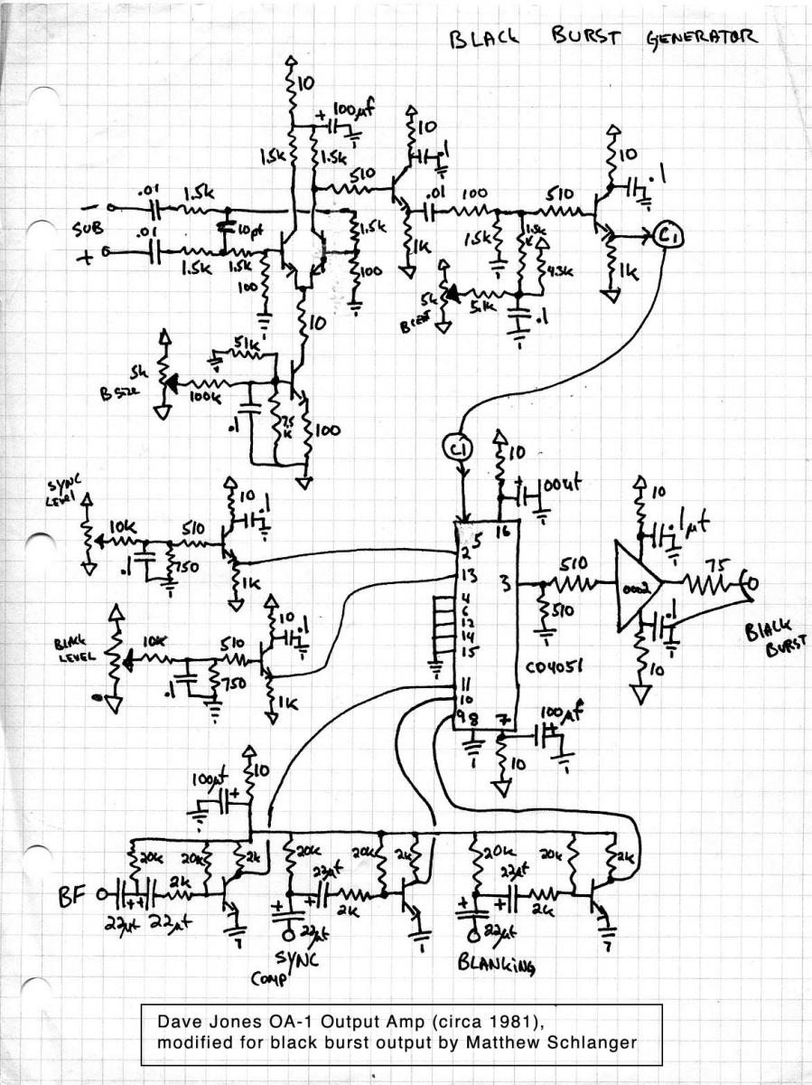
Black Burst Generator
It is important to distinguish between black burst and burst. Black burst is a fully encoded video signal with black image content, while burst refers to the nine cycles of subcarrier that occur between the breezeway and back porch of composite video signals. The first four sync signals mentioned are utilized to create a composite video signal, which inherently contains these four signals. Composite sync is directly manifested in composite video, while subcarrier is included in the burst. The burst flag indicates when the burst occurs, and blanking determines the precise start of the front porch and end of the back porch.
As integrated circuits capable of decoding this information from composite video signals became more widespread, black burst—essentially a black video signal—emerged as a simpler method for distributing sync information. Using black burst allows a single wire to carry all necessary sync information for a device. The initial sync generator designed by Jones did not incorporate black burst functionality, prompting the need for an additional circuit as the modular synthesizer neared completion. This circuit was mounted on a small board added to the back panel and employs an eight-channel CMOS multiplexer/demultiplexer, specifically the CD4051.
The CD4051 multiplexer allows switching between eight different analog sources based on a three-bit binary word. It is bidirectional, enabling both multiplexing and demultiplexing, and it operates over a wide voltage range with adequate frequency response for composite video signals. In this application, only the subcarrier signal has significant bandwidth and connects to the output when both blanking and burst flag (BF) are active. The subcarrier passes through a differential amplifier derived from Dave Jones' output amplifier design, which includes gain and DC trimpots for adjusting burst size (from +20 IRE to -20 IRE) and burst centering.
When both blanking and composite sync are active, a DC voltage is routed to the output, adjustable via a trimpot to set the sync level (-40 IRE). Conversely, when blanking is inactive, a black level DC signal is sent to the output, with its own trimpot for adjusting the black level (7.5 IRE). In situations where blanking is true and both burst flag and composite sync are inactive, inputs tied to ground are connected to the output, defining the levels for the front porch, breezeway, and back porch. Additionally, buffers for the three pulse inputs invert the signals from low true to high true. This circuit is straightforward yet opens up various possibilities for future applications, including the potential use of a multiplexer to construct a sequencer.CMOS analog multiplexers were frequently used at the ETC for various purposes. Here I thought I would present a circuit I borrowed from a Dave Jones design, and slightly modified it, to build a black burst generator. Video systems need sync to ensure that all the devices are in time with each other, and sync is also a component of composite video.
In the less recent past sync signals included composite sync, subcarrier, blanking, and burst flag. In addition some devices, usually cameras, required horizontal and vertical drives. That`s six signals, all in time, created by a sync generator and distributed with distribution amplifiers. All are low true pulses except subcarrier, which is a 3. 58 MHz sinewave. Subcarrier is used to encode color content, it is present in the image component as chroma, and as a color reference in the burst.
Don`t confuse black burst with burst. Black burst is a fully encoded video signal with black for image content, burst is the 9 cycles of subcarrier that appears between the breezeway and the back porch of all composite video signals. As the first four sync signals mentioned above are used to create a composite video signal, a composite video signal has encoded within it the same four signals.
Composite sync is manifest directly in composite video, subcarrier is present in the burst, burst flag determines when the burst happens, and blanking will determine the precise location of the beginning of the front porch and the end of the back porch. As chips proliferated that were able to decode this information from a composite video signal, black burst, nothing more than a black video signal, became a ubiquitous simpler way of distributing sync information.
Using black burst, a single wire can carry all the sync information a device needs. My first Jones sync generator did not have black burst, so as I neared completion of my modular synth I realized I needed to add one. This circuit was built onto a small board that was added to the back panel. This circuit uses an eight channel CMOS multiplexer/demultiplexer, the CD4051. You can find the datasheet here:. This mux allows you switch between 8 different analog sources based on a 3 bit binary word. They are bidirectional so you can also use them to demultiplex as well as multiplex, they have a wide voltage range, and they have pretty good frequency response, sufficient for a composite video signal.
Of course here, there is only one signal with any bandwidth we are concerned with, subcarrier, that will connect to the output when both blanking and burst flag (BF) are true. Notice the subcarrier goes through a differential amp that I lifted from the Dave Jones output amp, and it has gain and dc trimpots that can be used to set the size of the burst (+20 ire to -20 ire) and the burst centering.
When blanking and compsync are true, a dc voltage is connected to the output. This voltage has a trimpot which can be used to set the sync level (-40 ire). When blanking is false the black level dc signal is connected to the output. It also has a trimpot which is used to adjust the black level (7. 5 ire). And in cases where blanking is true and burst flag and compsync are false inputs tied to ground are connected to the output which define the level for the front porch, breezeway and the back porch. Notice the buffers for the 3 pulse inputs also invert the drives from low true to high true. Simple, but you can begin to see the possibilities. In a future post I will describe how I used a mux to build a sequencer. 🔗 External reference
Related Circuits
Why an electronic cricket? Many people enjoy the sound of crickets, especially those living in urban areas. This electronic cricket circuit operates in pulses, creating a similar sound. The electronic cricket circuit is designed to replicate the natural sound of...
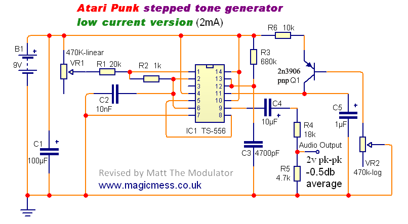
The Stepped Tone Generator is a dual oscillator circuit that produces a single pulse wave output. The first oscillator controls the pitch of the output oscillator, which divides the pitch into progressively smaller amounts based on its pulse width...
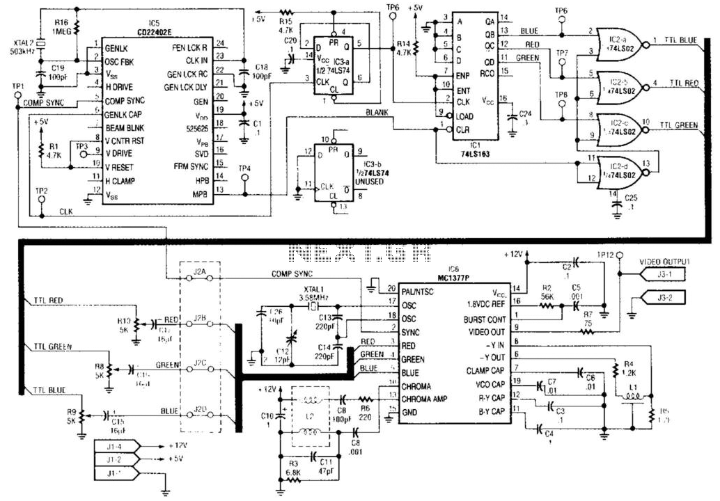
IC5 generates RS-170 NTSC synchronization signals. IC1, IC2, and IC3 are responsible for producing the red, green, and blue video signals that feed into the encoder section of IC6 to create color bars. IC3 functions as a 2-counter that...
Converting periodic waveforms to square waves is essential for extracting clock signals from data, creating waveform generators, and developing timing-pulse generators. A square-wave conversion circuit is more advantageous when the duty cycle of the square wave is variable and...
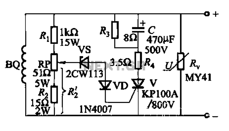
The DC voltage for the generator field winding is supplied by a three-phase thyristor rectifier. In instances of incorrect operation, phase misalignment, or system failure, the rectifier may generate hazardous conditions, leading to over-voltage insulation issues on the DC...
A simple triangle and square wave generator utilizing a common 1458 dual op-amp, capable of operating from very low frequencies up to approximately 10 kHz. The time interval for one half-cycle is determined by the product of resistance (R)...
Warning: include(partials/cookie-banner.php): Failed to open stream: Permission denied in /var/www/html/nextgr/view-circuit.php on line 713
Warning: include(): Failed opening 'partials/cookie-banner.php' for inclusion (include_path='.:/usr/share/php') in /var/www/html/nextgr/view-circuit.php on line 713