
Blinking LED Emulates Incandescent Bulb

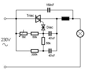
The flashing LED circuit designed to mimic an incandescent lamp operates by simulating the gradual increase and decrease in brightness that is typical of traditional incandescent bulbs. This effect is achieved using a microcontroller or a simple timing circuit that modulates the current flowing through the LED.
The core components of the circuit include an LED, a resistor to limit current, and a timing element, which can be implemented using a capacitor and a transistor or through a microcontroller’s PWM (Pulse Width Modulation) capabilities. The LED is connected in series with a current-limiting resistor to prevent it from drawing excessive current, which could lead to damage.
To create the flashing effect, the circuit utilizes a timing mechanism that controls the on and off states of the LED. When the LED is turned on, the current flows through the resistor, causing the LED to light up. As the timing circuit triggers the LED to turn off, the current ceases, and the LED gradually dims. This dimming effect can be further enhanced by adjusting the timing parameters, allowing for a more realistic simulation of the incandescent lamp's warm glow.
The overall design can be expanded with additional features, such as adjustable brightness levels or varying flash rates, to better suit specific applications or user preferences. This circuit can be effectively used in decorative lighting, automotive applications, or any scenario where a warm, incandescent-like glow is desired from LED technology.This is flashing LED circuit emulate the turning of incandescent lamp. The characteristic of incandescent lamp is that they can`t abruptly change the.. 🔗 External reference
Related Circuits
Colour temperature refers to the tonal quality or shade of light. White light, for instance, is subjective and available in various hues. This guide aims to assist in identifying the most suitable shade for specific situations. A "warm" white...
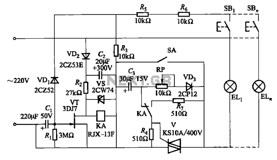
The circuit illustrated in Figure 2-50 utilizes a field effect tube and a combination of electronic components to create a unique self-lighting controller. The working lamp remains illuminated at a reduced brightness rather than being completely turned off, which...

The National LX5700 temperature transducer supplies input to a code conversion circuit that drives a 3-digit LED display. This display indicates temperatures ranging from -40°F to +100°F or -40°F to +199°F, controlled by a ganged switch. The National LX5700...

The schematic diagram and electronic assembly are relatively simple, as most of the functionality is managed by the microcontroller code. The schematic diagram serves as a visual representation of the electronic circuit, outlining the connections between various components such as...
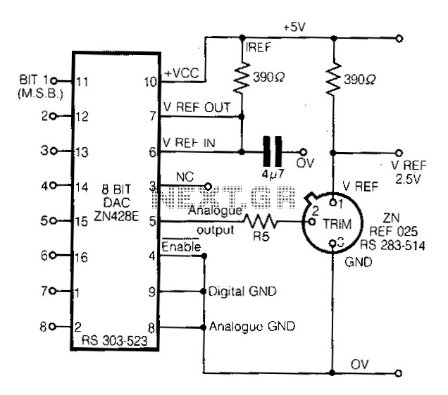
This circuit demonstrates a straightforward approach to achieving a voltage reference that can be adjusted using an 8-bit Digital-to-Analog Converter (DAC) equipped with an integrated voltage reference. The analog output from the DAC controls the trim pin of the...
An 18-year-old electrical engineering student, Chris Rieger, has been developing his levitating light bulb project, aptly named the LevLight Project, for approximately six months. Recently, he shared images and a video of the project, which gained significant attention on...
Warning: include(partials/cookie-banner.php): Failed to open stream: Permission denied in /var/www/html/nextgr/view-circuit.php on line 713
Warning: include(): Failed opening 'partials/cookie-banner.php' for inclusion (include_path='.:/usr/share/php') in /var/www/html/nextgr/view-circuit.php on line 713