
Booster for Cable Radio
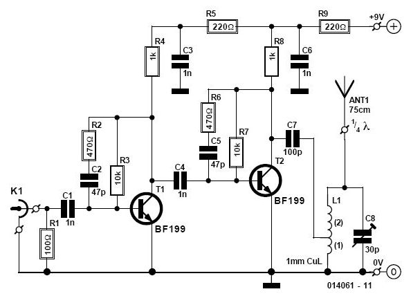
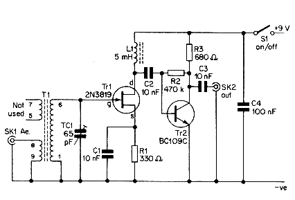
This circuit operates by modulating the audio signals from the local cable network onto a carrier frequency suitable for VHF FM transmission. The design typically includes an audio input stage, a modulation circuit, and an antenna for broadcasting the modulated signal.
The audio input stage captures the audio signal from the local cable network. This can be achieved using a line-level input, which connects directly to the audio output of the cable box or similar device. The signal may require amplification to ensure adequate levels for modulation.
The modulation circuit is crucial as it converts the audio signal into a frequency-modulated signal. This is often accomplished using a voltage-controlled oscillator (VCO) that varies its output frequency based on the input audio signal. The VCO is tuned to a frequency within the VHF band, allowing the signal to be picked up by standard VHF FM radios.
An important consideration in the design is the choice of components, particularly the VCO and the filter circuits that may be used to ensure that the modulated signal remains within the desired frequency range and minimizes interference. Additionally, the circuit may incorporate a low-pass filter to eliminate any unwanted high-frequency noise generated during modulation.
The antenna plays a critical role in transmitting the modulated signal. A simple dipole or monopole antenna can be used, designed to match the operating frequency of the VHF band. Proper placement of the antenna can significantly affect the range and clarity of the received signal on the portable radio.
Overall, this circuit provides a practical solution for accessing local cable network audio content through conventional VHF FM radios, making it a versatile tool for enhancing audio accessibility.With the aid of this circuit it is possible to listen, using a portable VHF FM radio, to listen to stations that transmit only your local cable network. Bo.. 🔗 External reference
Related Circuits
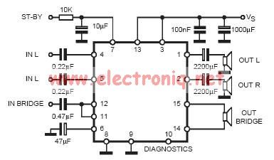
In practical applications, a series resistance must always be included. This component serves the dual purpose of limiting the current at pin 7 and smoothing the ON/OFF transitions during standby. In electronic circuits, particularly those involving integrated circuits (ICs) or...
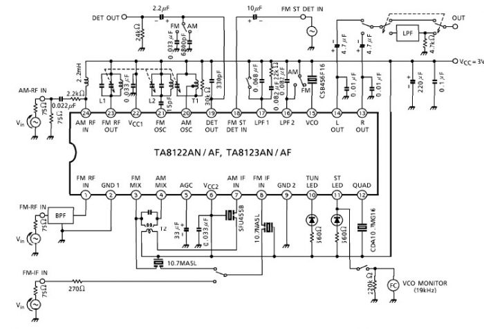
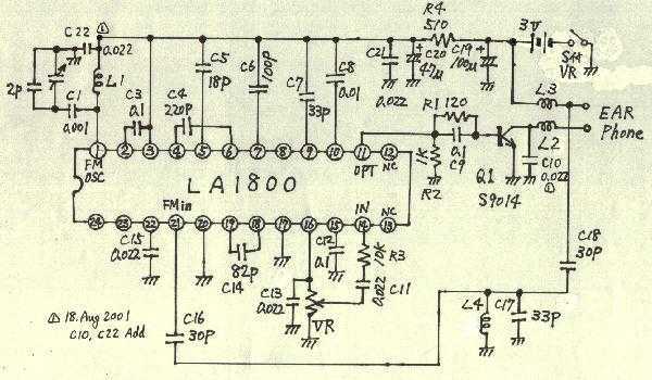
A simple low-power AM/FM radio receiver electronic project can be designed using the TA8122 integrated AM/FM receiver, manufactured by Toshiba Semiconductor. This radio receiver circuit is suitable for portable radio applications or other similar devices. The TA8122 radio receiver...
An RF field indicator is needed to verify power stages and transmitter antennas. This radio field indicator allows for the measurement of radiated energy from antennas. An RF field indicator is a crucial device in the field of telecommunications and...
Earphones, batteries are sold separately. AM / FM seems to be a common mold. But stamping is different. AM / FM E193577 UL94V0 board with the AM / FM etching printed circuit board manufacturers are the same. Shape is...
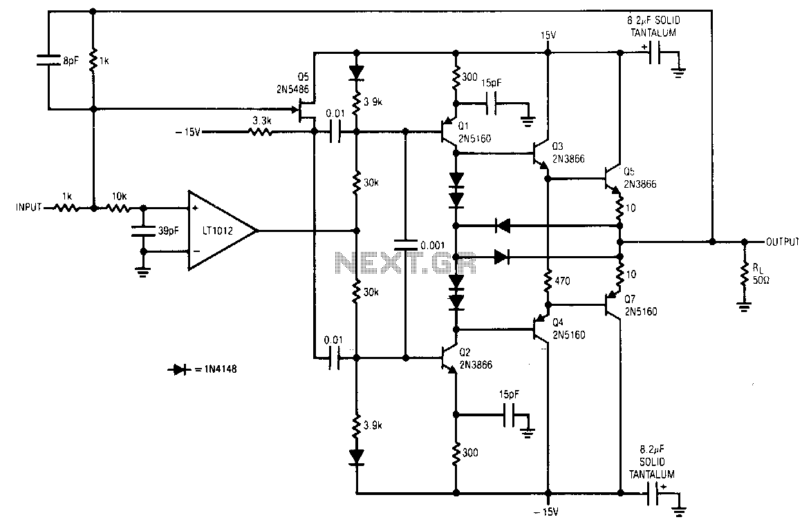
The LT1012 corrects errors in the booster stage and does not set high-frequency signals. Fast signals are fed directly to the stage via Q5 and the 0.01 µF coupling capacitors. DC and low-frequency signals drive the stage via the...
This simple aerial booster circuit design could serve as an alternative or a hobby project for creating an aerial booster device for Citizen Band (CB) radio. The aerial booster circuit is designed to enhance the performance of Citizen Band (CB)...