
BQ24020 battery charger
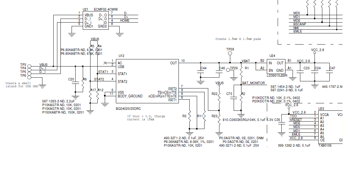
The BQ24020 is a highly integrated Li-ion battery charger capable of managing the charging process efficiently. In this application, it is essential to ensure that the STAT1 and STAT2 signals accurately reflect the charging status of the battery. The observed issue may stem from incorrect voltage divider ratios or improper configuration of the charger IC. A review of the voltage divider circuit, ensuring it aligns with the processor's 2.8V operating level, is advisable. Furthermore, verifying the configuration of the BQ24020, including the settings for termination and charge current, could resolve the false indication of a fully charged battery.
For battery status monitoring, the selection of an alternative IC that provides an interrupt signal at a defined voltage level is critical. Options such as the MCP73831 or the LTC4054 may be suitable, as these devices offer low-power operation and can signal when the battery voltage falls below a specified threshold, allowing the processor to manage power consumption more effectively without continuous polling.
Regarding the backlight driver for the TFT LCD, a suitable component should be selected that meets the requirements of driving dual LEDs with a common configuration. The MAX16832 or the LT3915 are examples of compact LED drivers that can handle the specified current and voltage while offering PWM dimming control. Ensuring that the driver maintains an efficiency greater than 85% will be crucial for optimizing battery life, particularly in portable applications. The design should also account for the thermal management of the driver to prevent overheating during prolonged operation.
In summary, careful consideration of the BQ24020 configuration, selection of an appropriate battery monitoring IC, and the choice of a compact, efficient backlight driver are essential steps in addressing the outlined challenges in this electronic design.I am using BQ24020 charger IC to charge 120mAh Li-ion battery. I set the charge current to around 100mA. Attached is the circuit schematic. The problem I am facing is STAT1 and STAT2 signals indicate that battery is fully charged even though battery charge in progress and charging with desired current. I have put voltage divider circuit for status signals because the processor works at 2. 8V. Please suggest a solution. By considering battery status monitoring feature, I am planning to select different IC that provides interrupt signal on certain battery level (typically 3. 3V) to indicate low battery. Otherwise I need to poll a signal to monitor the battery level continuously, such activity doesn`t allow processor to sleep draining battery.
Please suggest a part which has compact package and takes care of this feature. Also I have requirement of backlight driver for TFT LCD. Backlight contains dual LED (but with common cathods and anode) and requires 30mA at 3. 3V to operate at full intensity. I want control the intensity by using PWM signal coming from processor. The input to the driver is 2. 8V. The efficiency of the driver should be more than 85% and the part should be compact. Please suggest a part. All content and materials on this site are provided "as is". TI and its respective suppliers and providers of content make no representations about the suitability of these materials for any purpose and disclaim all warranties and conditions with regard to these materials, including but not limited to all implied warranties and conditions of merchantability, fitness for a particular purpose, title and non-infringement of any third party intellectual property right. TI and its respective suppliers and providers of content make no representations about the suitability of these materials for any purpose and disclaim all warranties and conditions with respect to these materials.
No license, either express or implied, by estoppel or otherwise, is granted by TI. Use of the information on this site may require a license from a third party, or a license from TI. Content on this site may contain or be subject to specific guidelines or limitations on use. All postings and use of the content on this site are subject to the Terms of Use of the site; third parties using this content agree to abide by any limitations or guidelines and to comply with the Terms of Use of this site. TI, its suppliers and providers of content reserve the right to make corrections, deletions, modifications, enhancements, improvements and other changes to the content and materials, its products, programs and services at any time or to move or discontinue any content, products, programs, or services without notice.
🔗 External reference
Related Circuits
This circuit is intended for charging lead-acid batteries with a solar panel. The customary diode that prevents the battery from discharging through the solar panel has been replaced by a FET-comparator combination. The charger will stop charging once a...
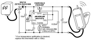
The diagram illustrates a Lithium-ion (Li-ion) battery charger designed using the MAX1879 single chip. This charger offers a simple and cost-effective solution for charging single-cell Li+ batteries without generating heat. The MAX1879, when paired with an AC linear transformer...
The charger design resembles that of many commercially available chargers. It comprises a mains adapter, two resistors, and a light-emitting diode (LED). This type of charger is effective in practical applications. Resistor R1 has dual functions: it establishes the...

This simple circuit consists of a transformer, two diodes, a capacitor, and an ammeter. To charge a battery, connect the positive and negative terminals of the circuit to the corresponding terminals of the battery. When the battery is not...
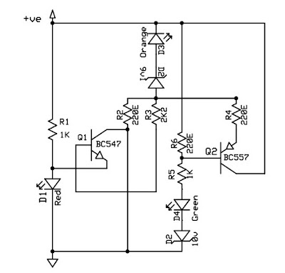
This circuit is a 12V battery checker that utilizes three LEDs to indicate different voltage levels. The red LED illuminates when the battery voltage is between 8V and 10V, the orange LED activates at voltages ranging from 10.5V to...
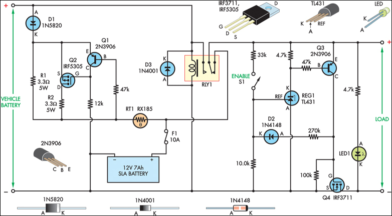
The SLA battery is charged from the vehicle's battery. When the engine is running, the voltage remains fairly constant, which greatly simplifies the charging circuit. If the SLA battery is fully charged, any further charging current from the vehicle...