
Breath-alert-alcohol-tester
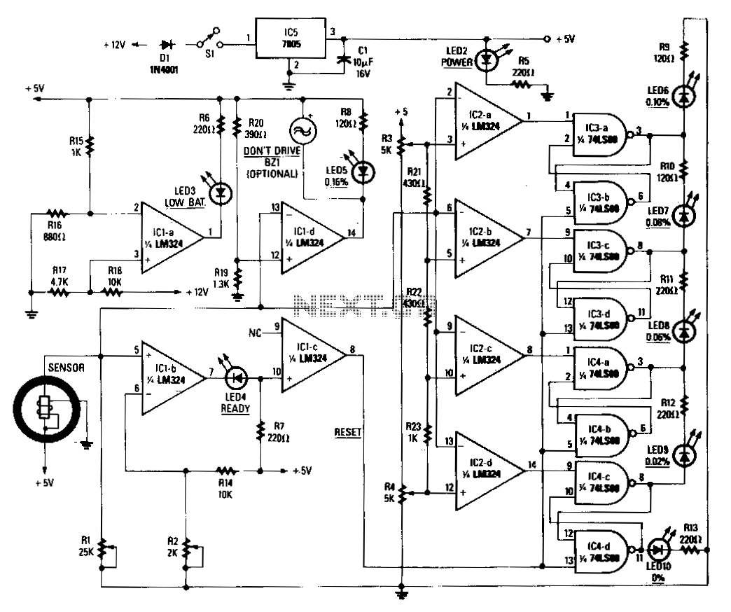
When power is applied to the circuit, the heater coil in the sensor is energized by the 5-V output of IC5, a 7805 voltage regulator. Breathing into the sensor with alcohol on one's breath will lower the sensor's resistance; consequently, the input voltage to the detector circuit will change. The detector circuit consists of a quad op-amp, IC2, and its associated circuitry. All sections of the detector circuit are calibrated via R3 and R4, and the inputs to each section are controlled by the voltage-divider network R21 through R23. As each section is triggered, the outputs decrease, and sample-and-hold circuits, IC3 and IC4, will latch onto the highest input value and drive the appropriate LED. The different colored LEDs represent alcohol levels from 0 to 0.16%. If the level of alcohol is above the legal limit, or 0.16%, part of another quad op-amp, IC1d, will turn on both the optional buzzer and LED5. That is an indication of a high level of alcohol present in the blood, and one should not drive. After a test is taken, the sensor takes a few seconds to ready itself for another test. When the sensor is ready, its input to IC1b, adjusted via R2 to a threshold of 0.5 V, causes LED4 (ready) to light. That, in turn, causes IC1c to reset the rest of the circuitry. The last section of IC1 is biased via R15 and R16 and is used to indicate a low-battery condition when the battery voltage drops below 6.8 V, which could result in an inaccurate breath test.
The circuit is designed to provide a reliable method for detecting alcohol levels through breath analysis. The initial energization of the heater coil by the 5-V output from the 7805 voltage regulator (IC5) ensures that the sensor operates within the required temperature range, enhancing its sensitivity to alcohol vapor. The reduction in sensor resistance upon inhalation of alcohol results in a measurable change in input voltage to the detector circuit, which is composed of a quad op-amp (IC2). This op-amp configuration allows for precise signal amplification and processing, with calibration facilitated by resistors R3 and R4 to ensure accuracy across different conditions.
The voltage-divider network formed by resistors R21, R22, and R23 plays a crucial role in controlling the inputs to the various sections of the detector circuit. As the sensor detects varying alcohol concentrations, the quad op-amp outputs respond accordingly, with lower output levels indicating higher alcohol concentrations. The sample-and-hold circuits (IC3 and IC4) are integral in capturing the peak input values, thereby ensuring that the corresponding LEDs reflect the highest detected alcohol level.
The system is equipped with a safety feature that activates an audible buzzer and an LED (LED5) if the alcohol concentration exceeds 0.16%, which is the legal limit for driving in many jurisdictions. This feature serves as a critical warning to the user regarding their fitness to drive. Following the breath test, a brief recovery period allows the sensor to stabilize before it can perform another measurement. During this time, the readiness of the sensor is indicated by LED4, which is activated when the input to IC1b exceeds the predetermined threshold set by R2.
Additionally, the circuit includes a low-battery detection mechanism through the final section of IC1, which monitors the battery voltage. When the voltage falls below 6.8 V, the circuit signals a low-battery condition, alerting the user to the potential for inaccurate readings due to insufficient power. This comprehensive design ensures that the breathalyzer operates effectively, providing accurate alcohol level readings while also incorporating essential safety features for user awareness.When power is applied to the circuit, the heater coil in the sensor is energized by the 5-V output of IC5, a 7805 voltage regulator. Breathing into the sensor with alcohol on your breath will lower the sensor"s resistance; consequently, the input voltage to the detector circuit, will change.
The detector circuit consists of quad op amp, IC2 and its associated circuitry. All sections of the detector circuit are cahbrated via R3 and R4, and the inputs to each section are controlled by the voltage-divider network R21 through R23. As each section is triggered, the outputs decrease, and sample-and-hold circuits, IC3 and IC4, will latch onto the highest input value and drive the appropriate LED. The different colored LEDs represent alcohol levels from 0 to 0.16%. If the level of alcohol is above the legal limit, or 0.16%, part of another quad op amp, IC1d, will turn on both the optional buzzer and LED5.
That is an indication of a high level of alcohol present in your blood, and you definitely should not drive. After a test is taken, the sensor takes a few seconds to ready itself for another test. When the sensor is ready, its input to IC1b, adjusted via R2 to a threshold of 0.5 V, causes LED4 (ready) to light.
That, in turn, causes IC1c to reset the rest of the circuitry. The last section of IC1 is biased via R15 and R16, and used to indicate a low-battery condition-when the battery voltage drops below 6.8 V-which could result in an inaccurate breath test. 🔗 External reference