
Bridge motor drive circuit
The bridge motor drive circuit is designed to control the direction and speed of a DC motor using a H-bridge configuration. The circuit consists of four transistors arranged in a bridge formation, allowing for efficient control of the motor's operation. The transistors are typically N-channel MOSFETs or bipolar junction transistors (BJTs) capable of handling the required current and voltage levels for the motor.
The four terminals A, B, C, and D serve as inputs to the control circuit. When specific combinations of these inputs are activated, they switch the transistors on and off in a manner that determines the motor's direction. For example, activating terminals A and B may cause the motor to rotate in one direction, while activating terminals C and D would reverse the rotation. This configuration enables bidirectional control of the motor, making it suitable for applications requiring precise movement.
The control mode can be set to manual, allowing an operator to directly control the motor's direction using switches or buttons connected to the terminals. Alternatively, an automatic control mode can be implemented, where a microcontroller or other automation system manages the inputs based on pre-defined parameters or sensor feedback. This flexibility in control methods enhances the circuit's versatility for various applications, from robotics to conveyor systems.
Additionally, protective components such as diodes may be included to prevent back EMF generated by the motor from damaging the transistors. Heat sinks may also be necessary to dissipate heat generated during operation, ensuring reliable performance and longevity of the circuit. Overall, the bridge motor drive circuit provides an effective solution for controlling motor functions in a wide range of electronic and electromechanical systems. Bridge motor drive circuit Bridge motor drive circuit is shown, the driving stage of the circuit is 4 transistors. The control circuit is provided with four ends, through to A, B, C, D can control the forward or reverse rotation control. Control mode can be used manually or automatically.
Related Circuits
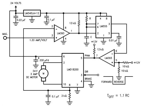
The LMD18200 3A H-Bridge, designed by National Semiconductors, can be used to create a simple motor controller electronic project suitable for motion control applications. This component is ideal for driving both DC and stepper motors, accommodating peak output currents...
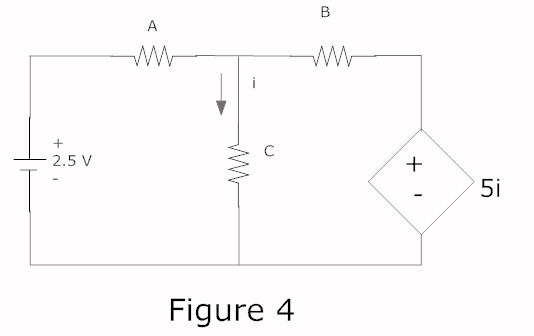
In a complete circuit, there are two types of elements: active and passive elements. Active elements generate energy, while passive elements dissipate energy. Examples of passive elements include resistors and capacitors. In electronic circuits, active and passive components serve distinct...
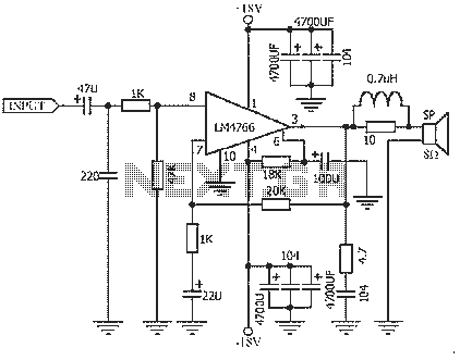
The NS LM4766, launched by a US company, is a two-channel power amplifier integrated circuit. Each channel can output an average power of 40W at an 8-ohm load, with distortion levels lower than 0.1%. It is part of National...
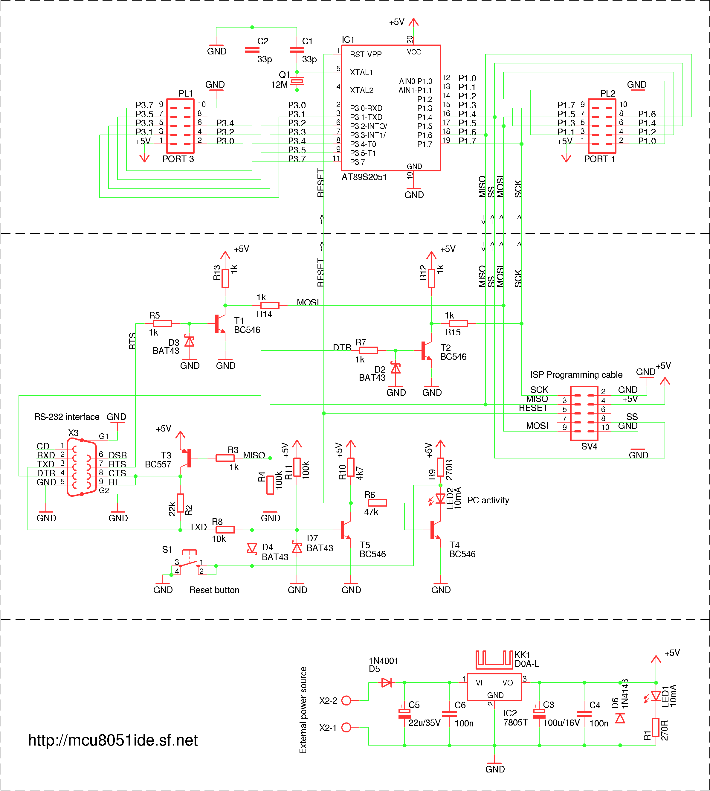
A simple RS-232 ISP programmer designed for AT89Sx devices, intended for educational purposes and hobbyist use. It has been tested with the AT89S2051 and AT89S8253 microcontrollers, utilizing a USB to serial port converter cable equipped with a PL2303 chip....
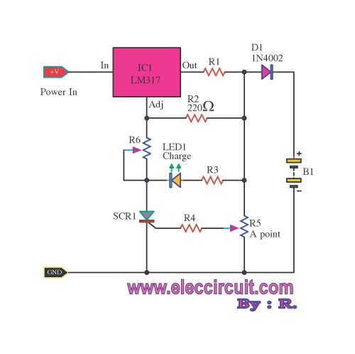
When building a lead-acid battery charger for a 6V or 12V battery, there are various methods available. One preferred option is the use of the IC LM317. The LM317 is a versatile adjustable voltage regulator that can be effectively utilized...
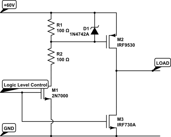
Construct an H-bridge specifically for reversing current, as speed control is managed separately. Is it feasible to connect two N-channel MOSFETs and two P-channel MOSFETs to an IO pin from the microcontroller (with appropriate resistors), or is the process...