
Bridge rectifier circuit in the electronic ballast application circuit
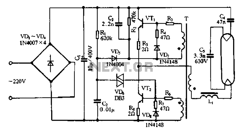
The bridge rectifier circuit is a crucial component in electronic ballast applications, primarily utilized for converting alternating current (AC) to direct current (DC). This conversion is essential for powering various electronic devices, particularly in lighting systems where precise control of current is necessary for optimal performance.
The typical configuration of a bridge rectifier consists of four diodes arranged in a bridge topology. This arrangement allows both halves of the AC waveform to be utilized, effectively doubling the output voltage and improving efficiency. The diodes are connected in such a way that during the positive half-cycle of the AC input, two diodes conduct and allow current to flow through the load in one direction. During the negative half-cycle, the other two diodes conduct, again allowing current to flow through the load in the same direction. This results in a pulsating DC output.
In an electronic ballast application, the bridge rectifier is often followed by a smoothing capacitor, which serves to reduce the ripple voltage in the output. This capacitor stores energy during the peaks of the rectified voltage and releases it during the troughs, providing a more stable DC voltage to the subsequent circuitry. Additionally, voltage regulators may be employed to further stabilize the output voltage and ensure compatibility with the electronic components being powered.
The design of the bridge rectifier must take into account the maximum input voltage and current ratings, as well as the thermal management of the diodes to prevent overheating. Proper selection of diode specifications, such as reverse voltage rating and forward current rating, is essential to ensure reliable operation under varying load conditions.
Overall, the bridge rectifier circuit plays a vital role in the functionality of electronic ballasts by enabling efficient energy conversion and stable power delivery to lighting systems, thereby contributing to energy savings and enhanced performance in lighting applications. Bridge rectifier circuit in the electronic ballast application circuit
Related Circuits
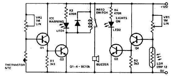
This electronic project circuit diagram for an ice warning and lights reminder system alerts drivers when their vehicle lights should be activated and warns them if the outside temperature approaches zero degrees Celsius. The system employs an LED indicator...
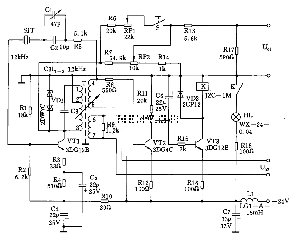
The circuit features a 12kHz intermediate frequency (IF) oscillator utilizing a quartz crystal for precision frequency generation. It includes components for output level adjustment, a level-up circuit, and an alarm circuit. The design employs a unique single-tuned variable feedback...
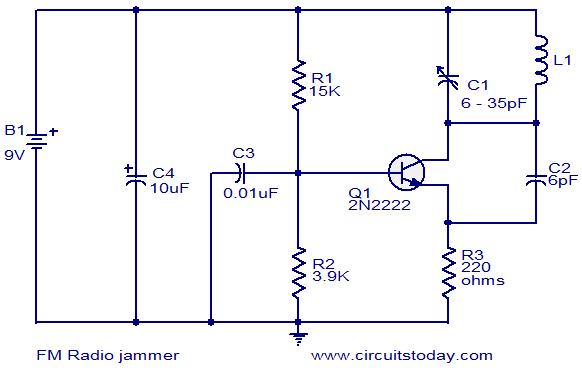
The FM jammer circuit diagram transmits VHF signals. Normally, the powerful oscillation of the circuit interrupts FM signals. Jammers are banned in many regions. The FM jammer circuit operates by generating a strong VHF (Very High Frequency) signal that disrupts...
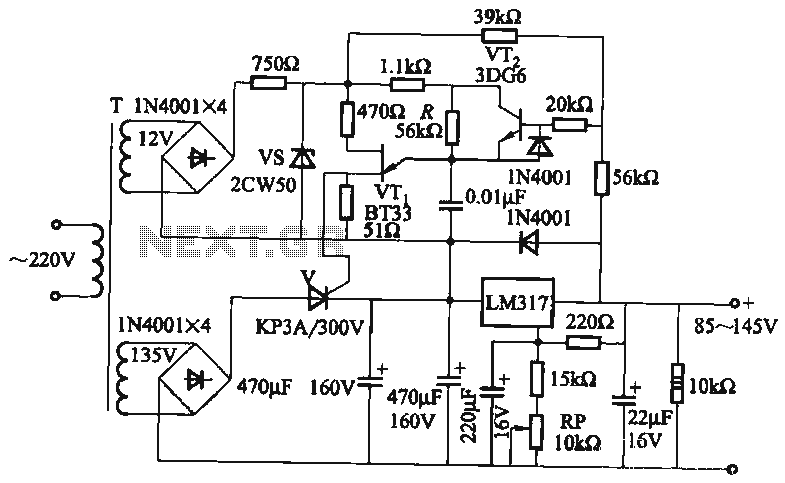
It utilizes a three-terminal adjustable voltage regulator power supply and incorporates a thyristor for presetting the LM317. The voltage can be adjusted between 85V and 145V, with an output current limited to a maximum of 1A. An adjustment potentiometer...
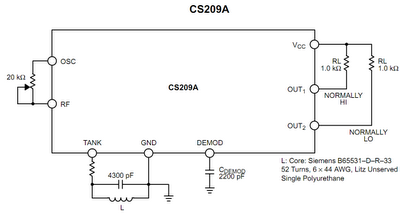
The operation principle of the proposed metal detector circuit is straightforward yet intriguing. The detection function is activated by sensing a decrease in the quality factor (Q) of the LC network associated with the circuit when a metal object...
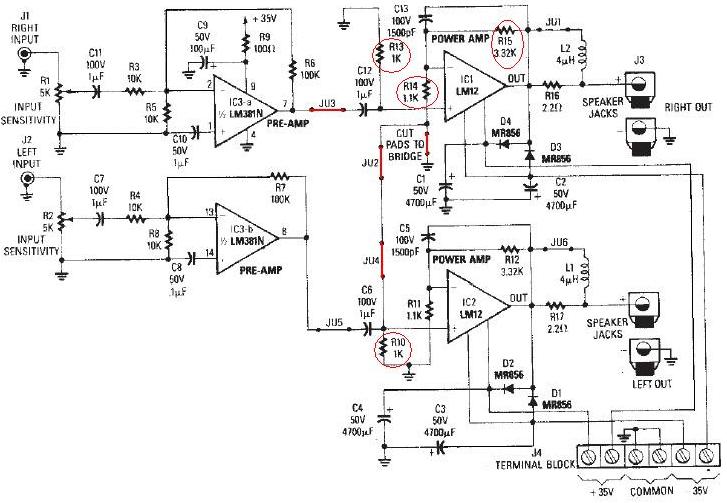
The LM12 audio amplifier circuit is designed to deliver high output power for 8 ohm or 4 ohm load impedances. The maximum output power provided by the LM12 audio amplifier is approximately 60 watts for a 4 ohm load...
Warning: include(partials/cookie-banner.php): Failed to open stream: Permission denied in /var/www/html/nextgr/view-circuit.php on line 713
Warning: include(): Failed opening 'partials/cookie-banner.php' for inclusion (include_path='.:/usr/share/php') in /var/www/html/nextgr/view-circuit.php on line 713