
BROADBAND MULTI-OCTAVE HIGH POWER AMPLIFIER
The MOSFET solid-state kilowatt amplifier represents a significant departure from traditional vacuum tube designs, focusing on the advantages of modern semiconductor technology. The use of MOSFETs allows for a more compact and efficient amplifier design, essential for amateur radio operators seeking high power output without the bulk and complexity of tube-based systems. The push-pull configuration employed in the design enhances linearity and efficiency, making it suitable for RF applications across the HF and six-meter bands.
In the schematic, the MRF154 MOSFETs are configured in a complementary push-pull arrangement, where one device handles the positive half of the waveform while the other manages the negative half. This arrangement not only improves power efficiency but also minimizes distortion, which is critical in high-fidelity RF applications. The input stage of the amplifier typically includes a matching network designed to optimize the impedance seen by the MOSFET gates, ensuring maximum power transfer and stability.
Thermal management is also a crucial aspect of the design, as even though MOSFETs are less prone to thermal runaway, they still require adequate heatsinking to dissipate the heat generated during operation. The amplifier's layout should facilitate airflow around the MOSFETs, and the use of thermal paste or pads can improve heat transfer to the heatsink.
Power supply considerations are paramount; a robust power supply capable of delivering the necessary voltage and current levels without sagging is essential for reliable amplifier operation. The design may incorporate voltage regulation to ensure consistent performance under varying load conditions.
Overall, the MOSFET solid-state kilowatt amplifier design not only revitalizes interest in solid-state devices for high-power applications but also exemplifies the evolution of amateur radio technology, merging innovation with practical engineering solutions. The continued exploration of newer MOSFET technologies and configurations promises to enhance the performance and reliability of future amplifier designs.A MOSFET solid state kilowatt amplifierplifier using MOSFET`s. Helge`s work was followed by articles that appeared in QEX and QST by Joel F. Paladino, N6AMG. Since then, very little has been written in amateur radio publications concerning MOSFET`s in kilowatt applications. Most kilowatt amplifier designs published, use vacuum tubes. These amplifiers tend to be bulky and heavy. In this article, I hope to renew interest in high power solid state RF devices. My primary objectives are to revisit the designs, investigate the use of newer devices, and offer a creative implementation of these devices in an amateur radio amplifier. Please keep in mind, this amplifier design is a work in progress. Previously, I contemplated building an amplifier using vacuum tubes. My requirement was for an amplifier in the 1000 Watt class for HF and six meters. In addition, I needed a power device that would handle this requirement. The device that came to mind was a Eimac 8877. I researched a design that would cover HF through Six meters. Every design was either for HF or Six meters, but not for both. In addition, they involved tube technology which I had not worked with in the past. The designs also looked a bit more mechanically complex than I had expected. My idea was to aim for a design that was both portable and straight forward to implement. After weighing the pros and cons, it looked like a solid state design was the only viable option left.
But which devices should I use Bipolars or MOSFET`s After a lot of reading, it seemed like MOSFET`s would be the device of choice. I decided to build one of the amplifiers designed by Helge Grandberg of Motorola. I had remembered reading of a design in QST, so I decided to go through all my piles of magazines. I finally found the article in the September 1992 issue. By looking at the schematic, everything looked very straight forward and simple. The device used was an MRF154 MOSFET in a push-pull configuration. MOSFET`s (Metal-Oxide-Semiconductor Field Effect Transistors) offer a lot of advantages over bipolar devices.
The main advantage is higher input impedances. This allows better matching networks to be incorporated, creating an amplifier with a broader bandwidth. In addition, they also offer superior stability than bipolars. Who wants an oscillating kilowatt amplifier MOSFET`s are also more robust than bipolars. MOSFET`s tend to be harder to overdissipate except when an overvoltage condition exists. MOSFET`s are also capable of more power per device. This makes kilowatt amplifiers easier to design without the need of complicated and lossy combiners. One disadvantage of Bipolars is that they suffer from thermal runaway. This means that current gain increases with temperature. In turn, this causes the device to draw more current as it gets hotter, thus causing an even greater temperature increase.
MOSFET`s are the opposite. Their gains decrease as temperature increases, causing the device to want to turn off. One drawback of FET`s is that their low order distortions are a little worse than those of bipolars. They do however, offer acceptable performance for ham radio use. . When the gate voltage is zero, these type of devices do not conduct current across the channel. The drain current increases with applied gate voltage. The name enhancement comes from fact that the channel is enhanced by an increased gate voltage; increasing drain current. These devices are analogous to a closed water faucet. Applying a voltage to the gate opens the faucet, increasing water flow. Water flow is equivalent to drain current in this example. . These devices conduct with zero applied gate voltage. The name depletion comes from the fact that the device channel needs to be depleted in order to reduce the drain current.
In "N"-Channel devices, a negative voltage is 🔗 External reference
Related Circuits
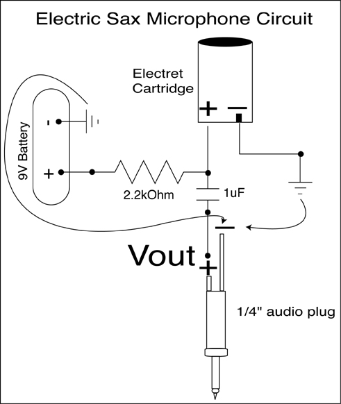
A condenser microphone (electret type with two terminals) is to be powered. A resistor of 1 kΩ and a capacitor of 10 µF have been connected to its positive terminal, while the other terminal is grounded. To power an electret...
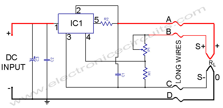
L200 Power Supply Regulator. There are applications in which it is important for the supply voltage to be largely independent of the load level. The L200 is a versatile voltage regulator designed to provide a stable output voltage while maintaining...
Circuit stereo TDA2822 audio power amplifier circuit schematics. In this series, the TDA2822M IC is utilized as the primary amplifier. Additionally, alternatives such as KA2209 and NJM2073 can also be employed. The TDA2822 audio power amplifier circuit is designed to...
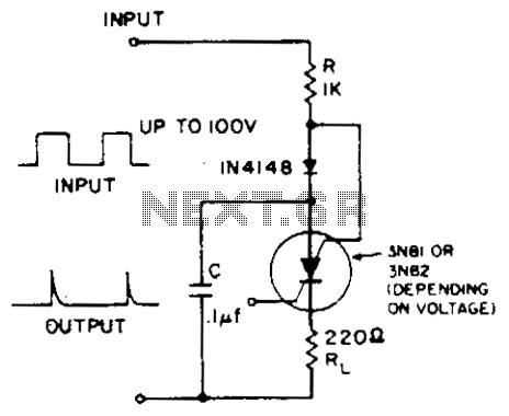
A positive-going input charges capacitor C through the IN4148 diode and resistor R. The diode ensures that the silicon-controlled switch (SCS) remains off. A negative-going input provides anode-gate current, which triggers the SCS, allowing capacitor C to discharge through...
This is a handy, easy to build general purpose 50 watt amp. The amp has an input for a radio, TV, stereo or other line level device. It also has a phono input for a record player, guitar, microphone...
High Quality unit with LM833 or NE5532 Low noise Dual Op-amp. No need for a preamplifier. Can be directly connected to CD players, tuners and tape recorders. Tested with several headphone models of different impedance: 32, 100, 245, 300,...
Warning: include(partials/cookie-banner.php): Failed to open stream: Permission denied in /var/www/html/nextgr/view-circuit.php on line 713
Warning: include(): Failed opening 'partials/cookie-banner.php' for inclusion (include_path='.:/usr/share/php') in /var/www/html/nextgr/view-circuit.php on line 713