
build a blinking safety light for your bicycle
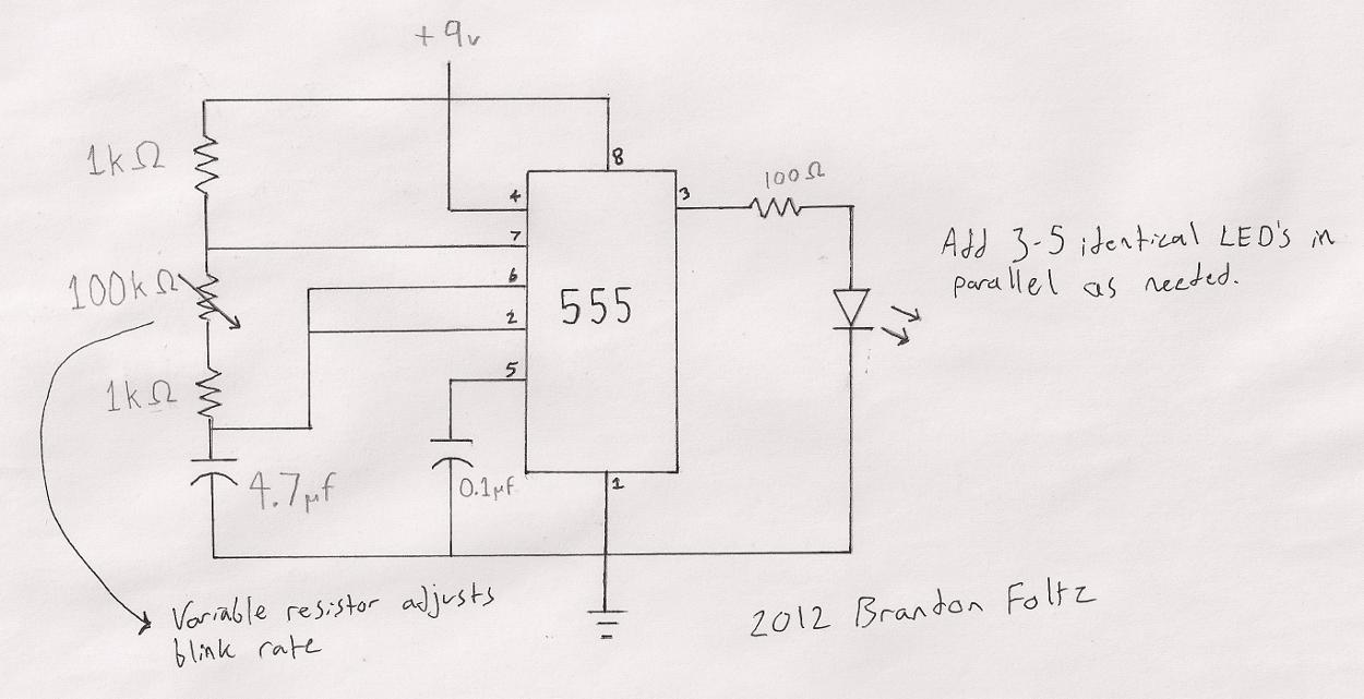
The circuit operates based on the well-known 555 timer IC, configured in astable mode to create a square wave output that controls the blinking of the LEDs. The variable resistor (trimpot) adjusts the timing of the output signal, thus varying the blink rate. The circuit can be powered by a 9V battery or an adapter, but care must be taken to ensure that the LED configuration matches the power supply voltage to avoid exceeding the voltage drop limits.
The schematic includes the 555 timer connected to a capacitor and resistors that determine the frequency of oscillation. The output pin of the 555 timer connects directly to the anodes of the parallel-wired LEDs, while the cathodes are connected to ground. This configuration allows each LED to receive the same voltage, ensuring they operate correctly regardless of variations in supply voltage.
For mounting, the enclosure should be designed to withstand environmental factors such as moisture and vibration common to bicycle use. Choosing a durable material and ensuring all components are securely fastened will enhance the longevity of the device. The design also allows for easy access to the trimpot for adjustments, ensuring that the user can modify the blink rate as needed while riding.
In conclusion, this LED blinker circuit is a practical application of the 555 timer, showcasing versatility in design and functionality while emphasizing user customization and ease of installation on a bicycle.The circuit I used is a very common one. You can do a google search for 555 timer LED blinker and find hundreds of schematis that will fit the bill. Here is the schematic for my particular flavor of LED blinker: The variable resistor (100K) in the schematic above may not be included in other designs with a fixed blink rate, I included it here so that the blink rate
can be user adjustable from about 1hz to several hundred hertz. I didn`t include mounting hardware in the parts list because you will need to do some thought on your own to decide how your enclosure will attach to your particular bicycle. My bike has a small metal piece above the rear tire with holes in it, so it was only logical to attach my enclosure here with a nut and bolt.
Wire this circuit up on your perfboard and insert it into your enclosure. Mount it on your bike and you`ll hopefully have something like this! Make sure you wire your LED`s in parallel! I had been testing the circuit on my breadboard with a 9v DC wall adapter as the power supply, this is slightly different from using a battery, as it will deliver ~14v to a lightly-loaded circuit. I had wired my LED`s in series, and with the wall adapter everything worked fine. However, when powered by a 9 volt, the four LED`s I had wired in series dropped more voltage than the 9 volt could deliver, so the circuit failed to operate.
The easy fix for this is of course to wire the LED`s in parallel, so that collectively they can only drop the same voltage as a single LED would (which is ~1. 5 volts). You can see how everything is laid out in the enclosure in the photo above. I soldered the circuit to the perfboard before cutting the excess off with a Dremel. The screw holes on the board don`t line up with the holes in the enclosure perfectly, so I only used one corner screw to hold it in place.
It`s a pretty tight fit for everything, but at least no space was wasted. I don`t have a photo of the back panel, but there is a quarter-inch hole for the bolt that is used to attach it to my bicycle. Your bike might not have the same mounting mechanism, so as I mentioned above you will have to figure out how to mount it yourself.
There is also a smaller hole directly above the screw head on the trimpot, this is so that you can adjust the blink rate with a screwdriver without ever taking the device off your bike. The finished project looks like this! 🔗 External reference
Related Circuits

A decrease in the resistance of the CDS cell when light strikes it activates latch A and B, enabling tone oscillator C and D, which produces an output of about 1000 Hz. RA sets the trip level. SI resets...

The circuit described is designed to activate a lamp when the telephone rings, provided that the ambient light is insufficient. It utilizes two integrated circuits (ICs) and can be implemented with ease. At the core of the circuit is...
This light dimmer control features active timing capacitor reset or AC line zero-crossing synchronization. The 13 additional components are common and cost less than $2. Performance at the low end is exceptionally smooth and snap-free, even better than the...
A dimmer for individual LED bulbs. LEDs (light emitting diodes) are very sensitive components; exceeding their rated current or voltage can drastically reduce their lifespan from over 50,000 hours to mere microseconds. LEDs are current-driven, meaning that the intensity...
The circuit consists of two building blocks. The first is a square wave oscillator made up of two transistors in a multivibrator arrangement and the second is a CD 4017 decade counter IC. The multivibrator contains two extra components...
The circuit detailed here counts the number of times an infrared beam is interrupted. It can be utilized to track the number of individuals entering a room or to monitor how frequently an object, such as a ball, passes...