
Build a Portable AM Radio Transmitter
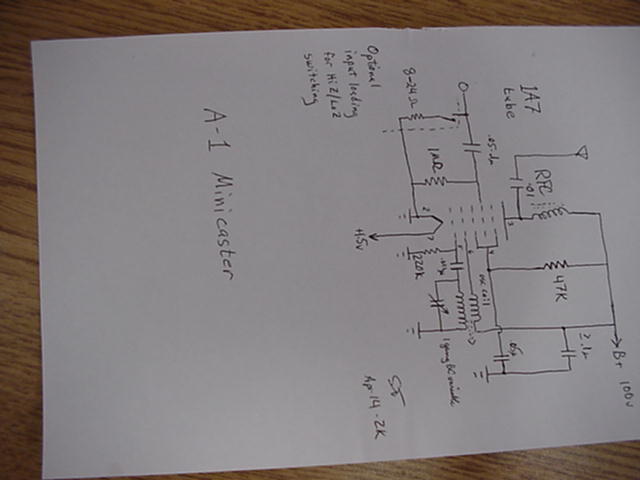
The A-1 Minicaster circuit is designed around the 1A7 vacuum tube, which serves as the primary active component in this portable transmitter. The circuit operates on a battery voltage of approximately 1.5 volts, making it suitable for portable applications. The connections for the tube's pins are as follows:
- Pins 1 and 2 are connected to ground, serving as the base shell and the A- terminal, respectively.
- Pin 3, designated for the plate, connects through an RF choke of greater than 1 mH to the B+ voltage source, with a capacitor of 0.01 µF leading to the antenna terminal. This arrangement helps to filter and stabilize the RF output.
- Pin 4, the screen grid, is connected through a 47 kΩ resistor to B+ and has a 0.05 µF capacitor to ground, which aids in maintaining a stable screen voltage.
- Pin 5, the oscillator grid, is linked to ground through a 220 kΩ resistor, and a 0.001 µF capacitor connects to the secondary winding of the oscillator coil, with the other end grounded. This configuration is essential for the oscillator to function effectively.
- Pin 6 connects the primary of the oscillator coil to B+, facilitating oscillation.
- Pin 7 is connected through one half of a double-pole single-throw (DPST) switch to the positive voltage, while the other half of the switch connects to B+. This switch allows for easy power control.
Additional features include a neon indicator (NE-2) across the B+ line to signal when the device is powered on. A low-resistance load, typically between 8 to 24 ohms, can be switched in or out across the RCA jack to ensure proper impedance matching with the audio source, such as a pocket-sized tape recorder. The overall construction of the A-1 Minicaster was creatively accomplished using an old cake pan, demonstrating a practical approach to building a functional radio transmitter.
This project is intended for non-commercial use by radio hobbyists, allowing for personal reproduction and experimentation with the provided instructions and schematic. Commercial exploitation of this design is strictly prohibited.After we published the original Li`l 7 AM Transmitter plans, fellow experimenter Scott Todd sent us information about his design for a similar portable, battery-powered transmitter. -Original Message- From: Scott Todd Sent: Wednesday, April 12, 2000 8:58 AM To: Walter Heskes Subject: A-1 minicaster I noticed that you have yet to get around
to developing a battery operated part 15 transmitter for swap meets (or if you have, it`s not on the net. ) Well, I decided to take matters into my own hands and did one myself. Actually it was nothing more than a variation on a converter circuit in a farm radio using a 1A7 (hence the name A-1 Minicaster.
) Since I`m no computer genius and don`t own a scanner, I`ll have to describe the schematic. Should be simple enough- Pins 1 & 2 [base shell and A- respectively] to gnd. Pin 3 [plate]- RF choke >1mH (will be replacing with tuned circuit for better performance and lower spurious output) to B+, and. 01 to antenna terminal. Pin 4 [screen] through 47K to B+, and. 05uF cap to gnd. Pin 5 [osc. grid]- 220K to gnd, and. 001u cap to secondary of osc. coil; other end of same to gnd. Pin 6 [osc "plate"]- primary of osc. coil to B+. Pin 7 through 1/2 DPST sw. to +1. 5v. The other half of the DPST switches B+. Cap grid- 1M ohm to gnd, and >/=. 05uF cap to input jack (RCA). Additional touches- NE-2 neon indicator across B+ for power on; a low resistance (8-24ohm) that can be switched in or out as needed across the RCA jack for proper loading of audio source, such as when using a small pocket size tape recorder speaker output jack for source of programming.
Built mine on an old cake pan that developed holes and was no longer useable. Scott Todd N0BST -Original Message- From: Scott Todd Sent: Wednesday, April 26, 2000 8:24 AM To: Heskes, Walter M. Subject: RE: A-1 minicaster Here`s the pix of the A-1 minicaster, top and bottom plus schematic. I didn`t have a DP switch, so I had to kluge a second SP underneath for the HV. Note the neon indicator for HV-on. Small cap to osc grid is. 001 (noticed it was too small to read on schematic. ) This radio construction project, including all descriptions, diagrams, photos, and the underlying electronic design, is published here for the noncommercial use of radio hobbyists.
You may print and reproduce these project instructions for your personal use. Commercial use of this material is strictly forbidden. 🔗 External reference
Related Circuits
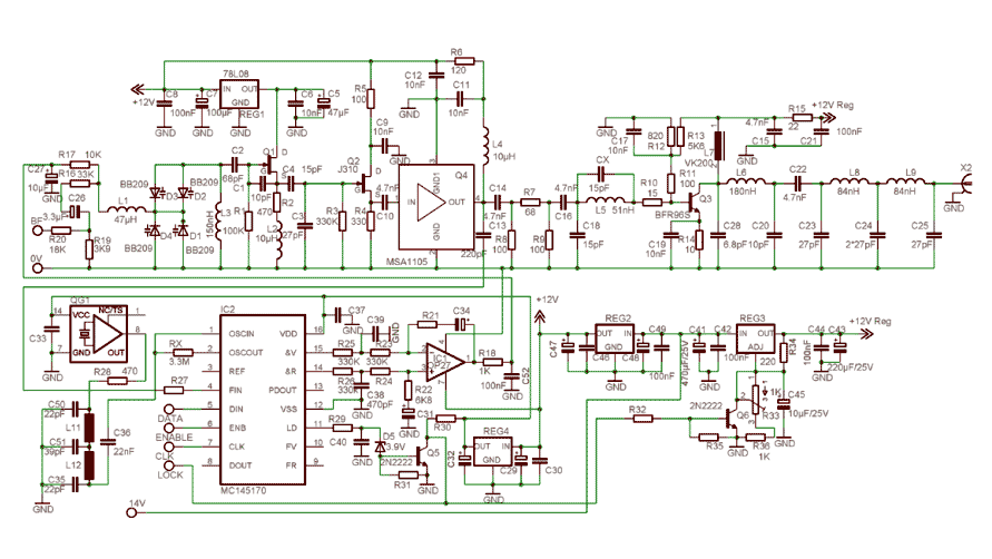
In order to simplify the transmitter design, we've used the new pll circuit from Motorola: the MC145170. This PLL includes the prescaler and a serial standard bus called SPI. We advise to use the P2 version that fixes some...
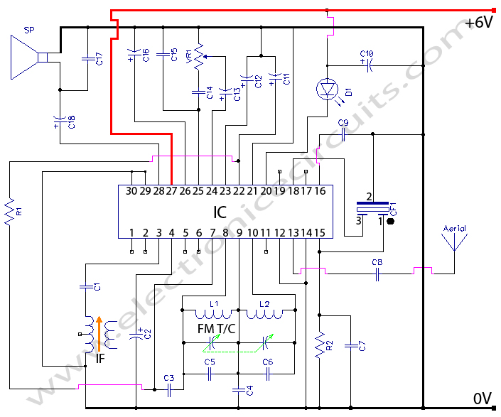
CXA1019 FM RADIO CXA1019 is a one-chip FM/AM radio IC designed for radio-cassette tape recorders and headphone tape recorders, and CXA1019S has the... The CXA1019 is an integrated circuit (IC) specifically engineered for FM/AM radio applications, particularly within radio-cassette tape...
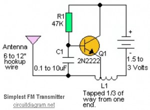
This is likely the simplest radio transmitter available. It comprises five components and can be assembled in a compact space. It is ideal for science fair projects or other science-related activities where short-range transmission is beneficial. The device operates...
This AM radio circuit is a low-power transmitter operating in the broadcast band. Its simplicity is achieved through the use of a single-transistor amplifier stage. The AM radio transmitter circuit operates within the standard AM broadcast band, typically ranging from...
A solar cell radio utilizes a 3V power supply, which can be provided by either a single 3V battery or two 1.2V Ni-Cad batteries connected in series. The battery is non-removable, and the device features a mini jack socket...
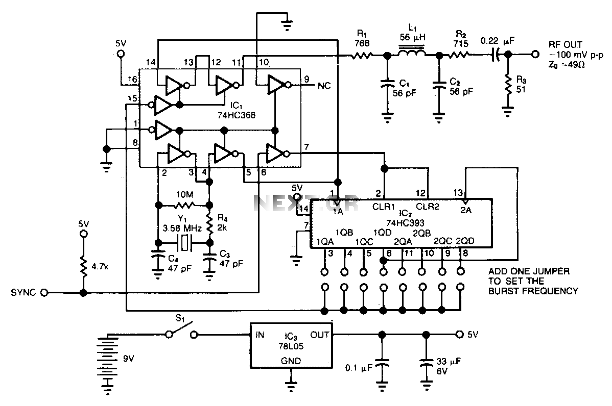
The circuit generates low-level RF bursts with frequencies up to 10 MHz, allowing for field testing of high-frequency receivers. A jumper-selectable binary fraction (1/2 to 1/256) of the Y1 crystal frequency gates the output RF signal. The output amplitude...