
Build an Servo Scales
The electronic scale design utilizing a servo motor incorporates several key components and principles. The servo motor operates based on a feedback control loop, which is essential for maintaining the desired position of the motor axle. The potentiometer serves as a position sensor, converting the mechanical position of the motor into an electrical voltage, which is then compared to the reference voltage derived from the PWM signal. This comparison is critical for ensuring the motor accurately reflects the weight applied to the weighing pan.
The square-wave oscillator generates a stable PWM signal at a frequency of around 50 Hz, which is crucial for the servo's operation. The fixed duty cycle of approximately 10% ensures that the motor remains in a defined position until a weight is applied. When a weight is placed on the scale, the resulting torque causes the motor to attempt to rotate, prompting the control loop to increase the power supplied to the motor to counteract this torque.
The design includes an ammeter in the servo supply line, allowing for direct measurement of the current drawn by the motor, which correlates with the weight on the scale. Calibration using known weights ensures that the system can accurately translate current readings into weight measurements. Additionally, the incorporation of a sense resistor allows for voltage output proportional to the current, facilitating further measurements and adjustments.
Using an instrumentation amplifier to address the quiescent current offset enhances the scale's accuracy. This amplifier can adjust the output signal to account for the inherent voltage present when there is no load, ensuring that the readings reflect only the weight applied.
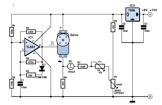
The design's flexibility is evident in the adjustable potentiometers, which allow for fine-tuning of the offset and weighing range, making it adaptable to various applications. The arm length is a critical factor in the design, as it influences both the torque and the accuracy of the scale; thus, careful consideration of this parameter is essential in achieving optimal performance. The suggested arm length of approximately 10 cm strikes a balance between accuracy and practical usability, making it suitable for most applications.With a bit of adeptness, you can build an electronic scales based on a servo motor. Depending on the type of servo you use, it can measure weights of up to around five kilograms (11 lbs) with reasonable accuracy. If you examine the operating principle of a servo motor in more detail (Figure1a), you can see that in simple terms, it consists of a control loop that
uses a potentiometer to convert the motor position to a voltage that is compared to the voltage from a PWM converter. Based in this information, the motor is rotated so that its measured position corresponds to the desired position (U2 = U1).
As can be seen from Figure1, all you need for a scales based on a servo motor is a square-wave oscillator that supplies a signal at a constant frequency of around 50 Hz with a f ixed duty cycle of approximately 10%. This defines a fixed setting for the position of the motor axle. If a mechanical force tries to rotate the motor axle in this situation, the servo control loop adjusts the drive signal to the motor to counteract the rotational force.
The motor thus has to supply an opposing force, and that costs power, with the result that the current through the motor increases. With a type RS-2 servo, this current can rise to as much as 1 A, while the quiescent current is no more than a few dozen milliampG¨res.
If you attach an arm to the motor axle and fit it with a weighing pan, and then connect an ammeter in the servo supply line, you have a sort of simple electronic scales. The scales can be calibrated using a reference weight, with the length of the arm set to produce a certain amount of current with a certain weight, such as 0.
5 A with 1 kg. Two kilograms would then draw 1 A, and so on. The scales can also generate a voltage out-put if you measure the voltage across a sense resistor in series with the ground lead of the servo (Figure1c). Due to the quiescent current consumption of the servo motor with no load, this voltage is not zero with no weight on the scales, but it is low compared with the value with a certain amount of weight.
Naturally, this offset can be compensated by using an instrumentation amplifier. This increases the accuracy, and you could even consider equipping the scales with a digital readout. Figure2shows a simple finished version with a PWM oscillator and analogue readout. The two potentiometers can be used to adjust the offset and weighing range. The length of the scale arm multiplies the torsion on the servo motor due to the weight. Doubling the arm length reduces the weighing range by half and thus doubles the accuracy, but it also increases the zero offset due to the weight of the arm.
In practice, an arm length of around 10 cm proved to be a good compromise. 🔗 External reference
Related Circuits
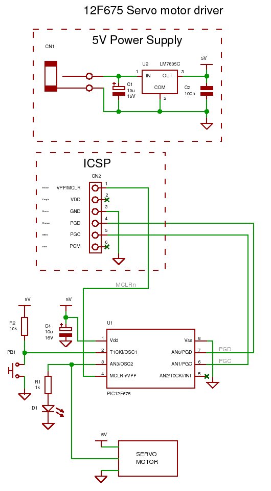
How to generate the signal for controlling a standard (RC) servo motor using a PIC microcontroller. To control a standard RC servo motor with a PIC microcontroller, it is essential to generate a pulse-width modulation (PWM) signal that dictates the...

AM radio receivers demodulate amplitude-modulated (AM) signals. The primary source of these signals is the Standard AM Radio Broadcast Band, although shortwave stations also utilize AM modulation. Amplitude modulation was developed between 1900 and 1917 by amateur radio enthusiasts....

The circuit for the Digital Tachometer/RPM Counter consists of a few components. They should be connected according to the provided circuit diagram. The PIC used is on a demonstration board, meaning the clock, power, and ground pins are already...

Before installing this or any other engine cut-off device in a vehicle, it is essential to carefully evaluate the safety implications of potential failures and the legal ramifications of implementing a device that could result in an accident. If...
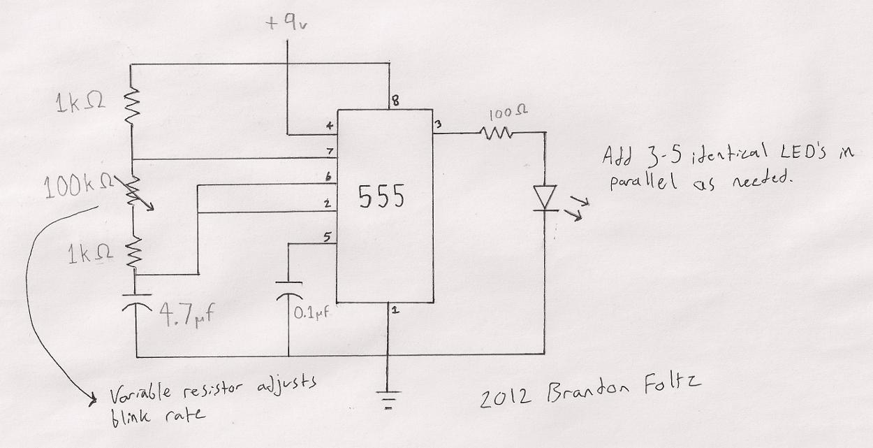
The circuit utilized is a commonly known design. A search for "555 timer LED blinker" will yield numerous schematics that are suitable for this application. The specific schematic presented includes a variable resistor (100K) that allows for user-adjustable blink...

Individuals who frequently work with servos are likely familiar with situations where a servo tester is beneficial. The primary function of a servo tester is to produce a pulsing signal with a variable positive pulse width ranging from 1...