
build program remote control
The HT6221 and HT6222 integrated circuits are designed for efficient data transmission in remote control applications, leveraging infrared technology for communication. The architecture of these ICs allows for a flexible configuration of inputs, enabling the encoding of a significant number of keys and corresponding data. The transmission process is initiated by the activation of a key, which triggers the encoding of the address and data into a format suitable for infrared transmission.
The key activation process is critical; it begins with a short press that enables the oscillator, allowing the device to prepare for transmission. The timing of various codes, including header and data codes, is meticulously structured to ensure reliable communication. The design of the output stage, particularly the use of resistors at the output pin, plays a vital role in determining the range of the infrared signal. By adjusting these resistor values, designers can optimize the performance of the remote control system, balancing power consumption and transmission distance.
Furthermore, the DOUT pin serves as the primary output for the encoded signal, modulating the infrared carrier frequency to convey the necessary data to the receiver. The LED indicator provides visual feedback, confirming that the transmission is occurring, which is essential during the development and testing phases of the project.
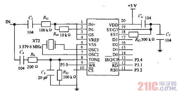
In summary, the HT6221 and HT6222 integrated circuits offer a robust platform for creating remote control systems, with features that support a wide range of applications. The careful design considerations in timing, output configuration, and user feedback mechanisms are crucial for ensuring effective and reliable operation in various environments.This project is based on integrated circuit from Holtek Semiconductor HT6221/HT6222. Similar parts used to be produced by NEC Semiconductor uPD6121/uPD6122. These ICs are commonly used in television and VCR infra red remote controls, garage door controllers, car door controllers, security systems and other remote control applications. They are cap able of encoding 16-bit address codes and 8-bit data codes. Each address/data input can be set to one of the two logic states, 0 and 1. The HT6221 can have keys up to 32(K1~K32) and HT6222 64 keys (K1~K64). When one of the keys is triggered, the programmed address/data is transmitted together with the header bits via an IR (38kHz carrier) transmission medium. This project provides the transmitter part of the remote control. Designers and hobbyists will have to do their own software at the receiver board. Those who are familiar with microcontroller programming will find this device easy to use. The features of this IC are: The typical 32 pins HT6221 schematic is as shown above. However, the values of 1k ohm and 47 ohm at the output pin 5 of the IC can be reduced to increase the distance the IR signal is transmitted.
After the transmission codes are sent, the DOUT pin generates transmission codes with a carrier, and the LED goes low to drive a transmission indicator. When one of the keys is triggered for over 36ms, the oscillator is enabled and the chip is activated.
If the key is pressedand held for 108ms or less, the 108ms transmission codes are enabled and comprised of a header code (9ms), an off code (4. 5ms), low byte address codes (9ms-18ms), high byte address codes (9ms-18ms), 8-bit data codes (9ms-18ms), and the inverse codes of the 8-bit data codes (9ms-18ms).
After the pressed key is held for 108ms, if the key is still held down, the transmission codes turn out to be a composition of header (9ms) and off codes (2. 5ms) only. 🔗 External reference
Related Circuits
This page outlines the hardware and software design of a printer power switch that is controlled via USB from a Linksys NSLU2, also referred to as Slug. Although primarily designed for printer control, the unit can manage any device...
The schematic presented below incorporates all the hardware components previously discussed. It is important to follow the tutorial precisely as shown. If a 220k resistor is unavailable, use the nearest higher value. Components are labeled to the best of...
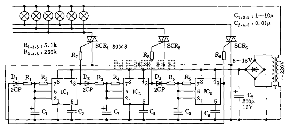
The circuit utilizes a 555 timer as its core component to control three lights through a cyclic trigger monostable delay circuit. The brightest light is controlled by a silicon-controlled rectifier (SCR) that determines the cycle of illumination. When pin...
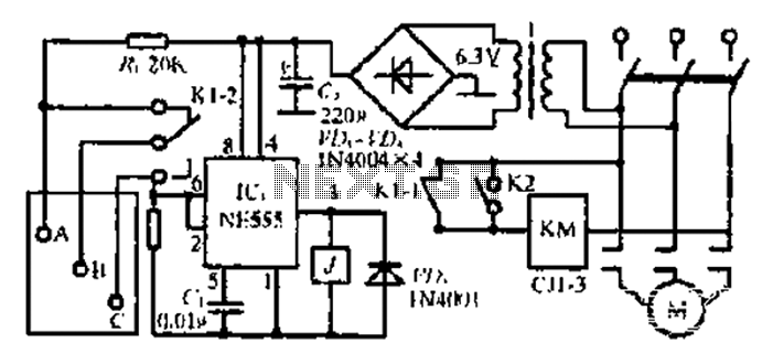
After the 3.40V power supply, the voltage is reduced to 6.3V through a full transition rectification using VDi and V sulfone. The C1 filter provides voltage stabilization after the caution circuit operates at the NE555 voltage level. When the...
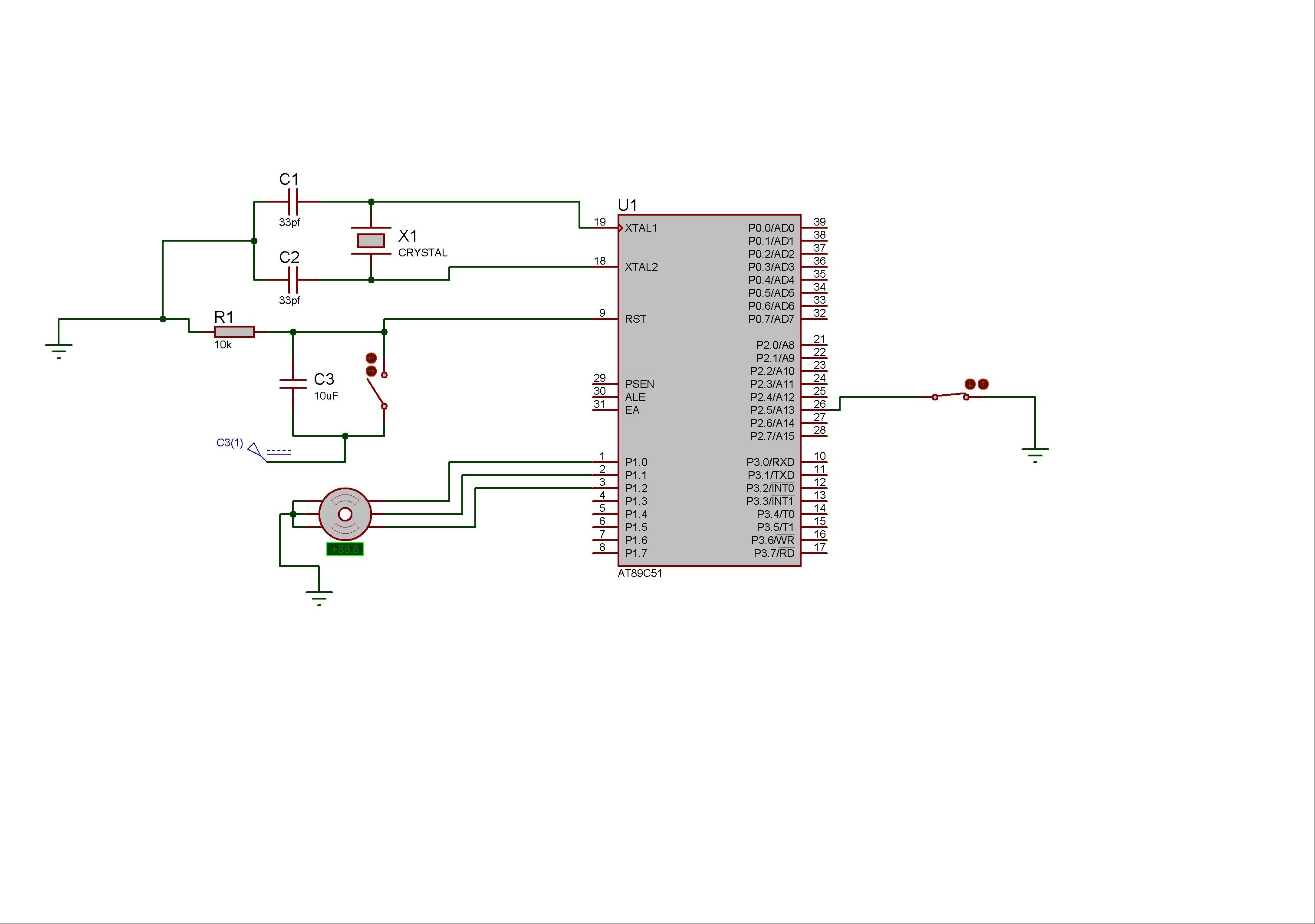
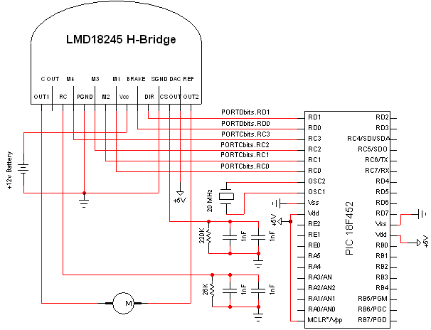
Stepper motors consist of a permanent magnet rotating shaft, known as the rotor, and electromagnets on the stationary part that surrounds the motor, referred to as the stator. One complete rotation of a stepper motor is illustrated. At position...
Precautions must be taken against low safety coefficients, as the applicable space for security measures continues to shrink. With advancements in science and technology, innovations such as magnetic door sensors, touch-type systems, radar monitoring, and infrared detection have emerged,...
Warning: include(partials/cookie-banner.php): Failed to open stream: Permission denied in /var/www/html/nextgr/view-circuit.php on line 713
Warning: include(): Failed opening 'partials/cookie-banner.php' for inclusion (include_path='.:/usr/share/php') in /var/www/html/nextgr/view-circuit.php on line 713