
build varying brightness ac lamp circuit
The varying brightness AC lamp circuit is designed to provide a flexible lighting solution by modulating the power supplied to a standard incandescent light bulb. The SCR plays a pivotal role in controlling the AC voltage applied to the lamp, effectively turning it on and off at a rapid pace, which results in perceived brightness changes. The integration of a 2K, 10-watt resistor is critical for voltage reduction, ensuring safe operation while also managing heat dissipation. Adequate ventilation is essential to maintain component integrity and prevent overheating.
The use of NPN transistors for half cycle detection allows for precise timing control, enabling the SCR to be triggered at calculated intervals. The 4017 decade counter serves as the core timing mechanism, with its outputs facilitating the adjustment of current levels, thus controlling the delay time before SCR activation. The design allows for a minimum delay of approximately 7 milliseconds, effectively rendering the lamp nearly off, while the full brightness state is achieved with minimal delay on the sixth output.
The circuit's ability to increment brightness in a linear fashion is enhanced by the configuration of resistors connected to the counter outputs, allowing for customizable brightness levels. This feature is particularly useful in applications where gradual light transitions are preferred, such as in mood lighting or theatrical settings.
The addition of a 47uF capacitor provides a smoothing effect on the brightness transitions, reducing the abrupt changes caused by the digital stepping of the counter. This enhancement results in a more aesthetically pleasing lighting effect, catering to user preferences for gradual dimming and brightening.
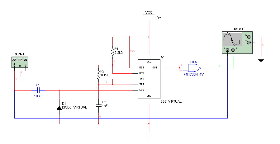
Overall, the varying brightness AC lamp circuit is a sophisticated solution for controlling light intensity, combining component selection and circuit design to achieve desired performance characteristics while ensuring safety and usability.Varying Brightness AC Lamp Circuit, an SCR is used to slowly vary the intensity of a 120 volt light bulb by controlling the time that the AC line voltage is applied to the lamp during each half cycle. The circuit is directly connected to the AC power line and should be placed inside an enclosure that will prevent direct contact with any of the components
. To avoid electrical shock, do not touch any part of the circuit while it is connected to the AC power line. A 2K, 10 watt power resistor is used to drop the line voltage down to 9 volts DC. This resistor will dissipate about 7 watts and needs some ventilation. A couple NPN transistors are used to detect the beginning of each half cycle and trigger a delay timer which in turn triggers the SCR at the end of the delay time.
The delay time is established by a current source which is controlled by a 4017 decade counter. The first count (pin 3) sets the current to a minimum which corresponds to about 7 milliseconds of delay, or most of the half cycle time so that the lamp is almost off. Full brightness is obtained on the sixth count (pin 1) which is not connected so that the current will be maximum and provide a minimum delay and trigger the SCR near the beginning of the cycle.
The remaining 8 counts increment the brightness 4 steps up and 4 steps down between maximum and minimum. Each step up or down provides about twice or half the power, so that the intensity appears to change linearly.
The brightness of each step can be adjusted with the 4 resistors (4. 3K, 4. 7K, 5. 6K, 7. 5K) connected to the counter outputs. The circuit has been built by Don Warkentien (WODEW) who suggsted adding a small 47uF capacitor from ground to the junction of the current source transistor (PNP) to reduce the digital stepping effect so the lamp will brighten and fade in a smoother fashion. The value of this capacitor will depend on the 4017 counting rate, a faster rate would require a smaller capacitor.
🔗 External reference
Related Circuits
This circuit utilizes a 555 timer to control a 4017 decade counter. The outputs from the counter are used to drive transistor relay drivers. The duration for which the lights remain "on" can be adjusted by modifying the connections...
Hello everyone. I need some help. I have constructed a PWM and PPM circuit. The output is functioning smoothly, but I am experiencing some problems and I am not very experienced. The PWM (Pulse Width Modulation) and PPM (Pulse Position...

The circuit described below is notable for its low power consumption. With a 9V input and no load at the output, it draws only 50 mA, which is significantly lower than the quiescent current of a 78L05 regulator. The...
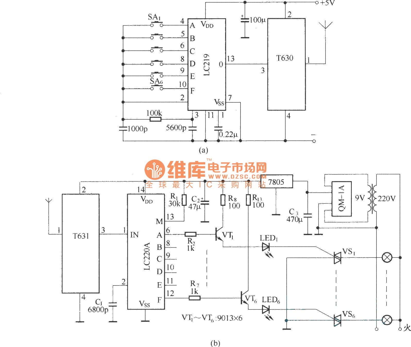
The circuit utilizes the long-wave wireless transceiver T630/T631 to manage a 6-channel load. It is characterized by low power consumption, high resistance to interference, and a simple structure. The circuit design incorporates the T630/T631 transceiver, which operates in the long-wave...
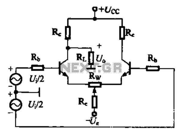
A comparison of four connection methods and features of a differential amplifier circuit is presented. The circuit demonstrates a magnification of a single tube with half the earnings, effectively countering common-mode negative feedback effects. The Common-Mode Rejection Ratio (CMRR)...
During rainy seasons, it can be quite bothersome when the car wipers operate continuously without pause. Have you ever considered implementing speed control for the wipers? While there are wiper control modules available commercially, many of them can be...
Warning: include(partials/cookie-banner.php): Failed to open stream: Permission denied in /var/www/html/nextgr/view-circuit.php on line 713
Warning: include(): Failed opening 'partials/cookie-banner.php' for inclusion (include_path='.:/usr/share/php') in /var/www/html/nextgr/view-circuit.php on line 713