
Build Your Own Motorcycle Alarm
This circuit is designed to enhance security for motorcycles through an effective alarm system that combines manual and automatic activation features. The intermittent siren output serves as a deterrent against theft, while the automatic reset function ensures that the alarm does not remain activated unnecessarily. The use of normally-open switches allows for flexibility in installation, accommodating various configurations depending on the motorcycle's design.
The integration of tilt switches adds an additional layer of security, as they can detect movement or tampering with the bike's position. The use of micro-switches to protect removable components further strengthens the system, ensuring that unauthorized access triggers the alarm. The low standby current is a crucial design consideration, as it prevents battery depletion when the motorcycle is not in use, thus maintaining the vehicle's readiness.
Resistors R7 and R8, along with capacitor C4, form a timing circuit that dictates the siren's activation and silence intervals. This adjustability allows users to customize the alarm's response based on personal preference or environmental considerations. The recommendation against using the motorcycle's horn highlights the importance of using a dedicated siren, which is less likely to be disabled by potential intruders.
The circuit's resilience to environmental factors is paramount; therefore, it is essential to protect the circuit board and switches from moisture. The placement of a 1-amp fuse close to the power source is a critical safety measure, safeguarding the circuit from overcurrent situations that could damage the wiring.
The installation process requires careful attention to detail, as variations in motorcycle designs necessitate customized approaches. The ability to monitor switch states through LEDs enhances user experience, providing visual confirmation of the system's status before arming the alarm.
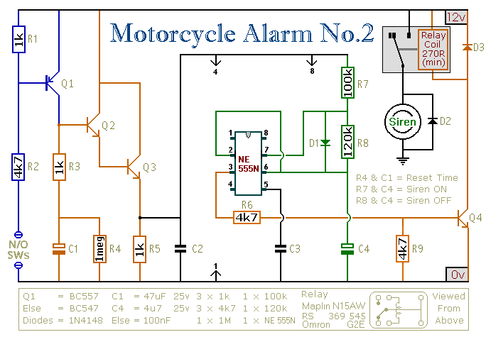
Overall, this alarm system represents a sophisticated approach to motorcycle security, incorporating user-friendly features and robust design elements to ensure reliability and effectiveness in protecting the vehicle. The accompanying support materials facilitate successful implementation, guiding users through each step of the construction and testing phases.This circuit features an intermittent siren output and automatic reset. It can be operated manually using a key-switch or a hidden switch; but it can also be wired to set itself automatically when you turn-off the ignition. By adding external relays you can immobilize the bike, flash the lights etc. I have used Andy`s Asymmetric Timer as the basis for this design. Any number of normally-open switches may be used. Fit "tilt" switches that close when the steering is moved or when the bike is lifted off its side-stand or pushed forward off its centre-stand. Use micro-switches to protect removable panels and the lids of panniers etc. The alarm`s standby current is virtually zero - so it won`t drain your battery. Once activated - the rate at which the siren switches on and off is controlled by R7, R8 & C4. For example, increasing R7 will make the sound period longer - while increasing R8 gives longer silent periods.
The circuit is designed to use an electronic Siren drawing 300 to 400mA. It`s not usually a good idea to use the bike`s own Horn because it can be easily located and disconnected. However - if you choose to use the Horn - remember that the alarm relay is too small to carry the necessary current.
Connect the coil of a suitably rated relay to the "Siren" output. This can then be used to sound the Horn, flash the lights etc. The circuit board and switches must be protected from the elements. Dampness or condensation will cause malfunction. Connect a 1-amp in-line fuse AS CLOSE AS POSSIBLE to your power source. This is VERY IMPORTANT. The fuse is there to protect the wiring - not the alarm. Exactly how the system is fitted will depend on the make of your particular machine - so I`m unable to provide any further help or advice in this regard. When you set the alarm - if one of the switches is closed - the siren will sound. This could cause annoyance late at night. A small modification will allow you to Monitor The State Of The Switches using LEDs. When the LEDs are all off - the switches are all open - and it`s safe to turn the alarm on. The components are all drawn lying flat on the board - but those connected between close or adjacent tracks are mounted standing upright.
The links are bare copper wire on the component side. Two of the links must be fitted before the IC. The Support Material for this circuit includes a parts list, a detailed circuit description, a step-by-step guide to construction and details of How To Test Your Finished Alarm. 🔗 External reference
Related Circuits

This manual provides instructions on how to utilize each component in the kit, along with software sketch examples for each. Users can combine components to create automatic systems, such as a lighting controller. The Arduino IDE software has a...

This power supply is suitable for a modular burglar alarm but can also serve other applications. It is designed to provide a 12-volt output with a current capacity of up to 1 amp. In case of mains failure, the...
When driving, it can be difficult to gauge the speed of a vehicle, particularly on straight highways. If the vehicle exceeds a safe speed, it may lead to accidents. Therefore, a Car Speed Alarm circuit is necessary to alert...

A two-tone generator that is alternately switched ON provides a high/low output similar to that of a traffic vehicle, such as a police car or ambulance. The CD4011 integrated circuit (IC1), which is a quad 2-input NAND gate, functions...

An AC drive controls AC induction motors and, similar to its DC counterparts, regulates speed, torque, and horsepower. A DC drive typically manages a shunt-wound DC motor, which features separate armature and field circuits. This teardown of the Schneider...
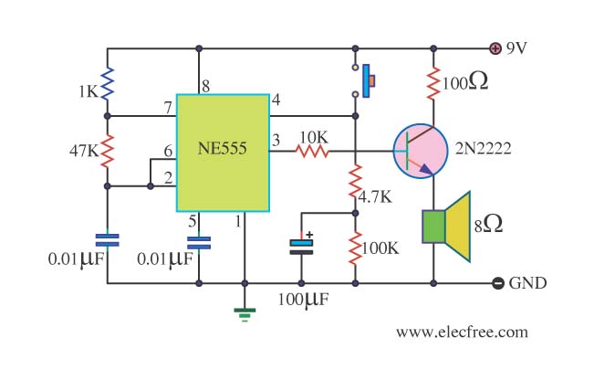
This is a danger beep circuit. It uses a 555 integrated circuit configured as a stable multivibrator that provides a duty cycle of 5% to drive a loudspeaker. The danger beep circuit utilizes the 555 timer IC, a versatile and...
Warning: include(partials/cookie-banner.php): Failed to open stream: Permission denied in /var/www/html/nextgr/view-circuit.php on line 713
Warning: include(): Failed opening 'partials/cookie-banner.php' for inclusion (include_path='.:/usr/share/php') in /var/www/html/nextgr/view-circuit.php on line 713