
building a gps logger
The proposed electronic system is designed to facilitate user interaction through a minimalistic interface comprising a single button and several LEDs, or alternatively, an RGB LED. This interface serves as the primary means of communication between the user and the device. The operational states of the device are clearly defined, with transitions initiated by user actions.
Upon pressing the button, the device transitions from a low-power sleep mode to an active operating mode. In this active state, a single press and release of the button allows the device to log the current GPS position as a waypoint. For power conservation, a prolonged button press of three seconds will re-engage the device into sleep mode. Additionally, the system is programmed to automatically enter sleep mode if it remains stationary for a duration of five minutes.
The data logging function is programmed to cease when the device is connected to a computer or when a GPS signal is lost. Importantly, the GPS receiver remains powered during sleep mode to ensure continuous signal lock, which is crucial until the battery reaches a critical level. Conversely, the SDCard interface is powered down during sleep mode to conserve energy.
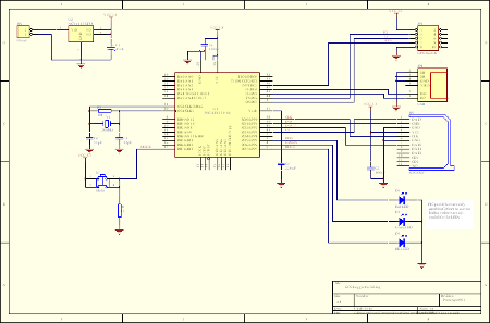
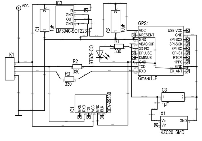
Exiting sleep mode results in the creation of a new log file, ensuring that data is organized and accessible. The hardware schematic includes essential components such as a PIC microcontroller, GPS interface, SDCard interface, USB connection, voltage regulation circuitry, and the user interface. However, the initial prototype does not include a battery, voltage monitoring, or charging circuitry, which are critical for a complete system.
The initial phase of software development will focus solely on the data logging functionality to evaluate the project's feasibility and gather necessary data for further requirements. Battery monitoring will be incorporated but will not control any operations, allowing for better power usage analysis. The software development will be carried out in a systematic manner, with each module being thoroughly tested before progressing to the next. Upon completion of all software sections, the prototype will be utilized to measure power consumption, which will inform the design of the final system and its battery specifications.The user interface will consist of a single button and several LEDs or a RGB LED through which all user communication will occur. An overview of the proposed system states and transitions is given below. Pressing the button will wake the device up from sleep and put it into operating mode. If the button is pressed and released in the operating mode, a waypoint of the current position is recorded into the log. Pressing the button for 3 seconds will put the device to sleep. The device will also go to sleep when in the same location for 5 minutes. Data logging will stop when the device is connected to a computer or GPS lock is lost. The GPS receiver will stay powered up while the device is in the sleep state to maintain signal lock until the battery level gets critical. The SDCard will be powered down during sleep. Coming out of sleep mode will create a new log file. A schematic of the prototype hardware is presented below and include the PIC, GPS interface, SDCard Interface, USB, Voltage regulation and User interface.
Missing from this version of the prototype is a battery, voltage monitoring and charging circuit. The initial software will consist of the data logging part only, to assess the viability of the project and to provide data for some of the requirements. Battery monitoring will be implemented but not control anything to provide better power usage figures.
The software will be written in the following order: Each section will be tested and confirmed working before the next section is started on. Once all sections are complete, the prototype will be used to gather power usage in order to design the final system and battery requirements.
🔗 External reference
Related Circuits
Following last year's rediscovery of radio-controlled flight, there is a growing interest in the hacking and modification potential of the budget-friendly 9-channel FlySky FS-TH9X transmitter (also marketed as Turnigy/Eurgle, etc.). The original 2.4GHz RF module and firmware are quite...
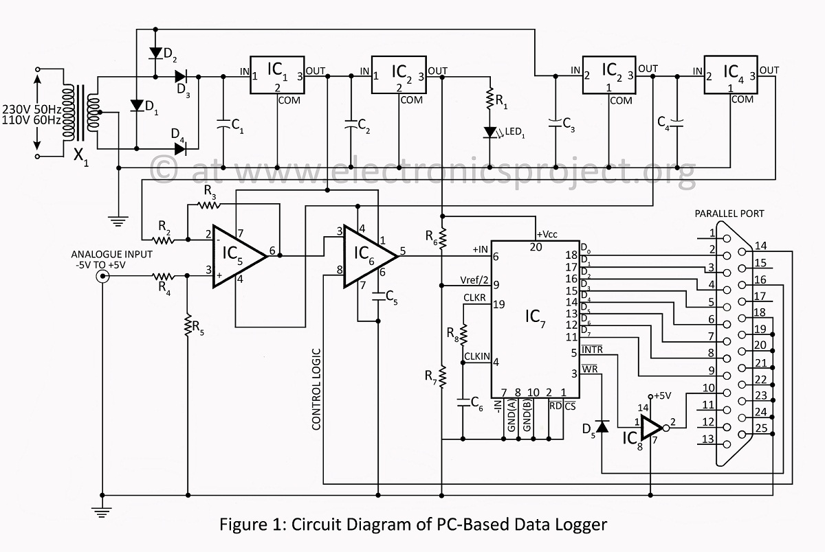
A PC-based data logger utilized in physics laboratories for automating simple experiments and monitoring slowly varying physical variables across various PC-based projects. The PC-based data logger serves as an essential tool in physics laboratories, enabling the automation of experiments and...
This application note presents the component values and measured performance for the MAX2681 mixer IC when tuned for GPS operation at 1575 MHz. The MAX2681 is a high-performance mixer integrated circuit designed for use in GPS applications, particularly at the...
A simplified block diagram of the MiniLOGGER is presented. The CMOS analog multiplexer, 4051, provides output for an 8-channel single-ended input to the analog-to-digital converter chip, CA3162, which operates in free-running mode. The digital output is a 4-bit BCD...
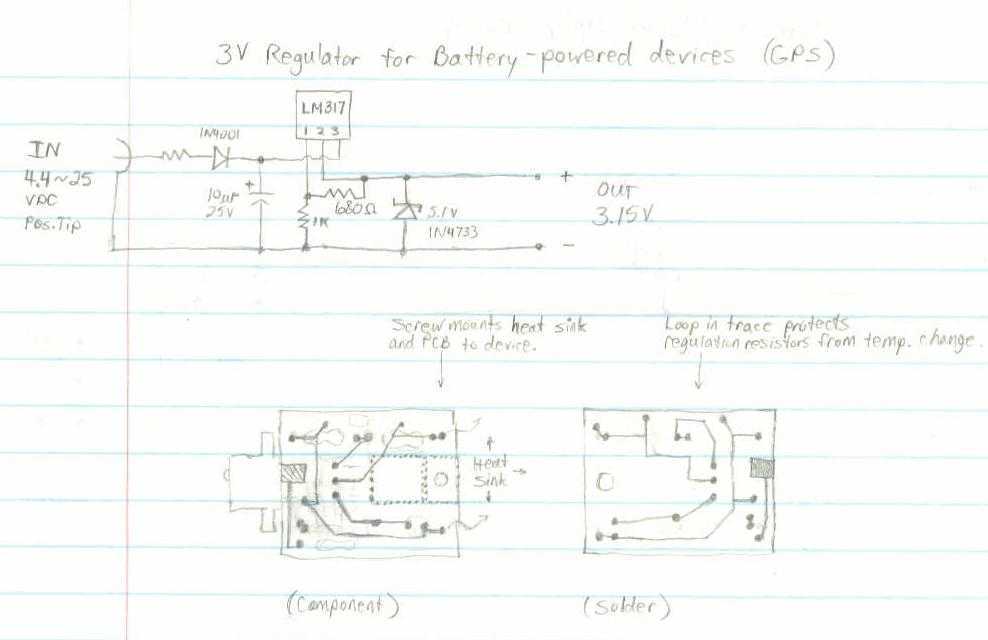
This GPS receiver is powered by 2 AA batteries. They are only strong enough for the GPS to stay on for about two hours, and this seems like quite a waste. I would like to be able to use...
The improved system is called RC-CAM2. It works better and it costs less than my earlier attempt to get a wireless video system on my flying model. The only caveat is that there is some assembly (or disassembly as...