
Building the poor-mans mini tesla coil
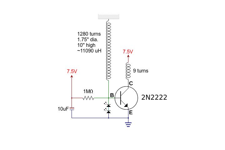
The circuit in question is a basic transistor circuit that serves as an introductory project for those learning about electronic components and their functions. The primary component, a transistor, acts as a switch or amplifier, depending on the configuration.
To construct the circuit, begin by identifying the type of transistor being used, whether it is a bipolar junction transistor (BJT) or a field-effect transistor (FET). Ensure that the transistor is oriented correctly, with the collector, base, and emitter (for BJT) or source, gate, and drain (for FET) properly aligned with the circuit schematic.
Next, gather the necessary materials, which typically include resistors, capacitors, and a power supply. Resistors may be used to limit the current flowing into the base of the transistor, while capacitors can provide stability and filtering in the circuit. The power supply should match the voltage requirements specified in the schematic to ensure proper operation.
Once all components are assembled, the wiring should follow the schematic closely, ensuring that all connections are secure and correctly positioned. It is advisable to use a breadboard for initial testing to allow for easy modifications if necessary. After wiring, double-check all connections before powering the circuit to prevent damage to components.
Upon successful assembly, the circuit can be tested by applying power and observing the behavior of the transistor. This may involve measuring voltage levels at various points or checking the output signal to confirm that the transistor is functioning as intended.
This simple circuit serves as an excellent foundation for understanding more complex electronic designs and principles.There is not much to this circuit. Above are all the graphics and pictures. After you gather all your materials, take your transistor and wire it up.. 🔗 External reference
Related Circuits
An SCR (Silicon Controlled Rectifier) functions similarly to a diode, allowing current to flow in one direction and can be turned on; it remains in this state until the power is interrupted. The query arises regarding its application in...
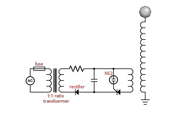
This circuit is designed to demonstrate high-frequency high voltage, capable of producing voltages up to approximately 30 kV, depending on the transformer used. It is economical and straightforward to construct, primarily utilizing a standard TV flyback transformer. The circuit...

This circuit is similar to the one found in the Single Buss 1V/Octave Keyboard Controller. Refer to the circuit description there for more details. This board includes additional resistors used in the keyboard voltage divider. In a typical keyboard,...
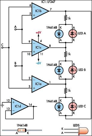
This circuit indicates which of three voltages, ranging from approximately -4V to +4V at points A, B, and C, is the highest by illuminating one of three indicator LEDs. Alternatively, it can be configured to indicate the lowest of...
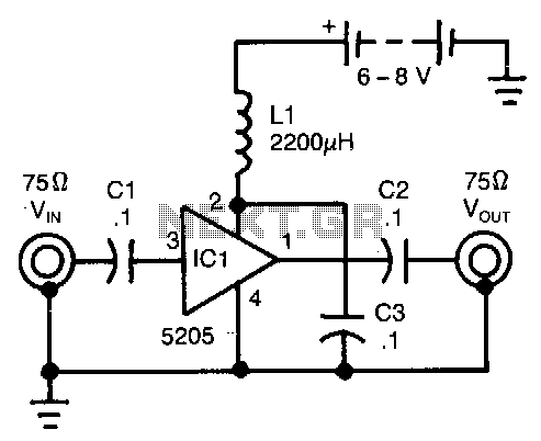
This wideband amplifier utilizes only five components. External signals are introduced to pin 3 of IC1 through an AC coupling capacitor, C1. After amplification, the enhanced signals from pin 1 of IC1 are transmitted to the output via capacitor...
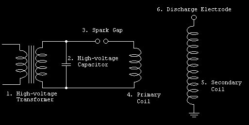
Tesla coils are air-core, resonant transformers that operate at high frequencies to generate immense voltages, resulting in spectacular lightning-like discharges. They are commonly utilized in the film industry to create effects that require lightning or electrical arcs. A notable...
Warning: include(partials/cookie-banner.php): Failed to open stream: Permission denied in /var/www/html/nextgr/view-circuit.php on line 713
Warning: include(): Failed opening 'partials/cookie-banner.php' for inclusion (include_path='.:/usr/share/php') in /var/www/html/nextgr/view-circuit.php on line 713