
Burglar-alarm
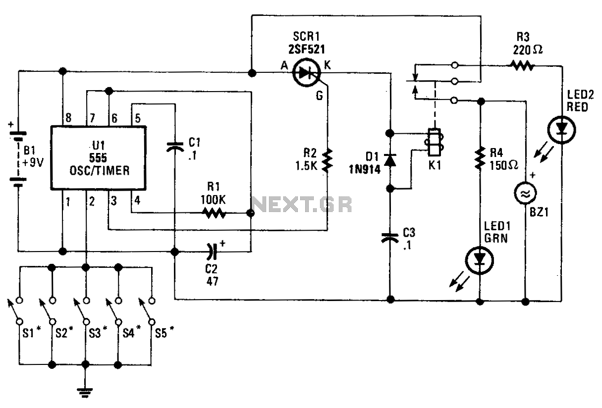
The core component of the circuit is a 555 timer/oscillator, designated as U1, which is configured for monostable operation. The output from U1 at pin 3 is connected to the gate of SCR1. As long as switches S1 to S5, which are linked to the trigger input of U1, remain open, the circuit stays in a standby state and does not activate SCR1 for conduction. Since the relay is not energized, the battery current flows through the relay's normally-closed terminal and through the current-limiting resistor R3 to LED2, causing it to illuminate. However, when any of the switches (S1-S5) is closed, pin 2 of U1 is grounded, resulting in an increased output at pin 3 of U1, which activates SCR1. This energizes the relay, moving the wiper of K1 to the normally-open terminal, which causes LED1 to light up and BZ1 to sound. The output duration is dictated by the RC time-constant circuit formed by resistor R1 and capacitor C1. Resistor R2 ensures that the output of U1 is regulated to a safe level for the gate of SCR1. Switches S1-S5 are intended for doors, windows, etc. An additional switch can be connected in series with the battery to activate and deactivate the alarm circuit when it is not required.
The described circuit utilizes a 555 timer in monostable mode, which is a widely used configuration for generating a single pulse output in response to a trigger signal. In this application, the 555 timer's output is crucial for controlling the behavior of a silicon-controlled rectifier (SCR), which serves as a switch for a relay. The relay plays a pivotal role in activating an alarm system, indicated by the lighting of LED1 and the sounding of buzzer BZ1.
The circuit is designed with safety and functionality in mind. The arrangement of switches S1 to S5 allows for multiple points of activation, such as doors and windows, enhancing the versatility of the alarm system. The use of a current-limiting resistor (R3) ensures that LED2 operates within safe limits, preventing damage while providing a visual indication that the system is armed.
The timing aspect of the circuit is governed by the RC components (R1 and C1). The time constant, τ = R1 * C1, determines how long the output at pin 3 of the 555 timer remains high after the trigger is applied. This feature is particularly useful for setting the duration of the alarm signal, allowing for customization based on user preference or application requirements.
Resistor R2 serves a critical function by protecting the gate of SCR1 from excessive voltage, ensuring reliable operation of the SCR when triggered. This protection is essential for the longevity and reliability of the circuit, preventing potential failures that could arise from over-voltage conditions.
Overall, this circuit exemplifies effective use of discrete components to create a reliable alarm system, with clear visual and audible indications of activation, and the flexibility to adapt to various security needs. The design can be further enhanced by incorporating additional features such as remote activation or integration with home automation systems.The heart of the circuit is a 555 oscillator /timer, Ul, configured for monostable operation. The output of Ul at pin 3 is tied to the gate of SCRl. As long as Sl-S5, which are connected to the trigger input of Ul, are open, the circuit remains in the ready state, and does not trigger SCRl into conduction. Because the relay is not energized, battery current is routed through the relay"s normally-closed terminal and through current-limiting resistor R3 to LED2, causing it to light.
However, when one of the switches (Sl-S5) is closed, grounding Ul pin 2, the output of Ul at pin 3 increases, artivating SCRl. That energizes the relay, pulling the wiper of Kl to the normally-open terminal, causing LEDl to light and BZl to sound.
The duration of the output is determined by the RC time-constant circuit, formed by Rl and Cl. Resistor R2 regulates the output of Ul to a safe value for the gate of SCRl. Switches Sl-S5 are to doors, windows, etc. A switch can be connected in series with Bl to activate and deactivate the alarm circuit when it"s not needed. 🔗 External reference
Related Circuits
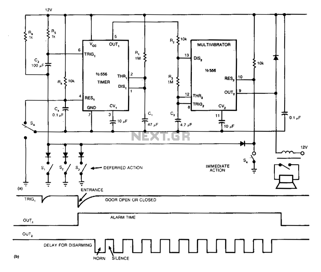
The single-chip burglar alarm circuit utilizes a dual 556 timer, drawing 10 mA of standby current, and produces a pulsing alarm signal that conserves battery energy. Once activated, the alarm remains operational, independent of the subsequent state of any...
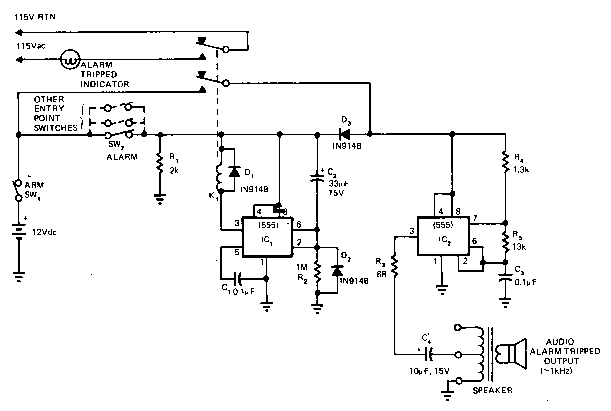
This circuit cannot be shut off for 10 to 60 seconds, even if the trip condition is immediately removed. It draws no standby power from the battery and is self-resetting. The described circuit operates under a delay mechanism that...