
Burglar Alarm System Project

The infrared burglar alarm system is designed to provide a reliable and user-friendly security solution. The core components include the transmitter, which emits infrared light, and the receiver, which detects the presence of this light. The TSOP1738 sensor is specifically chosen for its sensitivity to infrared signals, making it effective in detecting interruptions caused by intruders.
The circuit's power supply, rated at 6V DC and 500mA, ensures that it operates continuously without interruption. The use of low-cost components makes this project accessible for hobbyists and those looking to implement a basic security system without substantial investment.
LED2 serves as a power indicator, providing visual confirmation that the system is operational. The alarm triggering mechanism is initiated when the infrared signal from the transmitter is obstructed. This interruption causes the output of the TSOP1738 to transition to a low state, which is sensed by IC2. The role of transistor T2 is crucial as it acts as a switch that activates the alarm system. When triggered, the output at pin 7 of IC2 goes low, energizing the siren-driver transistor, which in turn activates the alarm sound.
The duration of the alarm can be customized by modifying the capacitance of capacitor C6. This flexibility allows users to set the alarm timeout according to their specific needs, whether for a short alert or a longer warning duration.
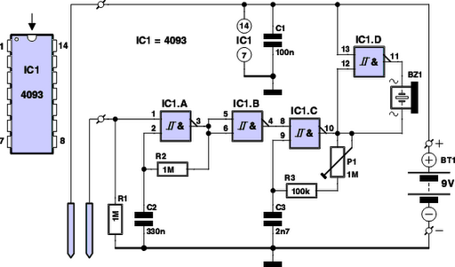
Installation involves assembling the transmitter and receiver circuits on separate PCBs, which can then be enclosed in protective cabinets to prevent damage. Proper mounting of the units is essential; they should be positioned directly across from one another at the entrance gate to ensure that the infrared beam is uninterrupted during normal conditions. This design not only enhances security but also provides an engaging project for electronics enthusiasts to explore and learn about circuit design and functionality.This burglar alarm system circuit is using a infrared proximity detector that triggers an alarm when the rays falling on its sensor are interrupted. It is different from others burglar alarm systems because is a very simple diy project and can offer you great satisfaction.
The circuit of IR burglar alarm system comprises transmitter and receiver-c um-alarm sections. It works off 6V DC, 500mA uninterrupted supply and uses low-cost readily-available electronic components. LED2 is used for indicating power-on. Check out the infrared alarm circuit too. The transmitted IR signal directly falls on IR sensor TSOP1738. Whenever the IR signal is interrupted, its output pin 3 goes low and IC2 is triggered at pin 5 through transistor T2.
As a result, its output at pin 7 goes low (for a preset time) to forward bias siren-driver transistor T2. This condition is indicated by the glowing of LED1. The time-out period can be increased or decreased by changing the value of capacitor C6. Assemble the transmitter and receiver-cum-alarm circuits on two separate general-purpose PCBs and house in suitable cabinets.
Mount the units on the opposite sides of the entrance gate such that IR rays from IR LED1 fall directly on the IR receiver module. hai, THIS PROJECT IS GOOD AND WE CAN UNDERSTAND SOMANY THINGS ABOUT THIS CIRCUIT DIAGRAM . CAN YOU PLEASE SEND THE DETAILED EXPLANATION ABOUT THIS PROJECT 🔗 External reference
Related Circuits

The circuit utilizes a 555 integrated circuit (IC) functioning as an astable multivibrator. When a positive 9 volts is applied to pin 8, the circuit generates sound through a speaker. The connection to pin 8 is routed through a...
Have you ever observed the stairs to an upper story in your house transform into a waterfall? Or perhaps you returned home to find your aquarium fish attempting to swim across the carpet? For your sake, it is hoped...

This circuit features open and closed loop contacts (switches 1, 2, 3) that activate the alarm, which remains on for a duration of 5 to 10 minutes. The triggering delay for entrance and exit is set to 27 seconds....

The SA607 is a low voltage, high-performance monolithic FM intermediate frequency (IF) system that includes a mixer, oscillator, two limiting intermediate frequency amplifiers, a quadrature detector, a logarithmic received signal strength indicator (RSSI), a voltage regulator, and audio and...
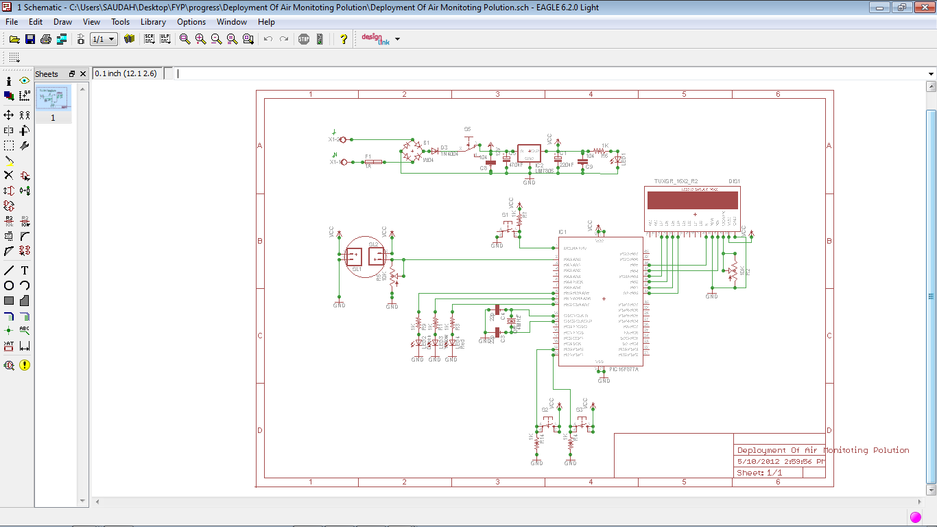
The PIC16F778A is widely used and is popular among both beginners and professionals due to its FLASH Memory technology, which allows for write/erase operations within thousands of programming cycles. This RISC microcontroller boasts advantages in speed and code compression...
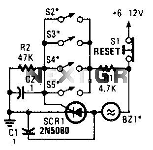
Four parallel switches are employed to monitor four positions. When any switch is closed, SCR1 is triggered, activating the alarm. The alarm is designed to be of the non-interrupting type. The circuit consists of four parallel switches, each representing a...