
By the driving capacitive loads MAX4223 ~ MAX4228 circuit diagram
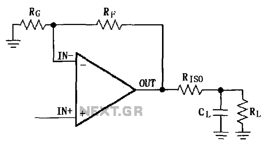
The MAX4223 to MAX4228 operational amplifiers are designed to handle capacitive loads effectively while minimizing signal distortion. The inclusion of the isolation resistor (RISO) is critical in preventing unwanted oscillations that can occur when driving capacitive loads. It acts as a damping element that reduces the Q-factor of the output stage, consequently lowering the amplitude of any overshoot or ringing that may arise when the output transitions.
In practical applications, the selection of RISO within the specified range of 5 to 20 ohms should be based on the specific load characteristics and the desired performance of the circuit. A lower resistance value may be suitable for applications where rapid signal transitions are necessary, while a higher resistance may be chosen to further suppress ringing at the expense of some speed.
The output stage of the MAX4223 to MAX4228 is engineered to deliver robust performance across a range of load conditions, making these devices suitable for various applications in signal processing, instrumentation, and control systems. Careful consideration of the capacitive load and the isolation resistor will ensure that the operational amplifiers perform optimally without introducing detrimental effects to the signal integrity. As shown in FIG grounds MAX4223 ~ MAX4228 uses a capacitive load drive circuit isolation resistor RISO constructed. MAX4223 ~ MAX4228 maximum permitted capacitive load of 25pF without overshoot ringing and ringing, there may be more than 25pF overshoot ringing and ringing. The circuit between the output terminals and the load plus an isolation resistor RISO, for suppressing overshoot and ringing oscillation, RISO resistance is 5 ~ 20 .
Related Circuits
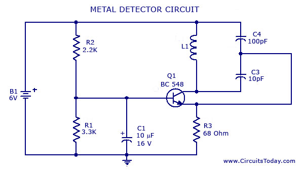
A simple metal detector circuit diagram and schematic using a single transistor and a radio. This metal detector/sensor project is easy to make and is an application of a Colpitts oscillator. The metal detector circuit utilizes a single transistor in...
This is a police tone circuit for a siren. It is simple and easy to construct. VR1 and VR2 are used to adjust the delay of the siren sound. The design is straightforward and uncomplicated. The police tone siren circuit...
The circuit consists of two 555 timer oscillators configured in a dual timer arrangement, both set up in astable mode. Components include a 1N4148 diode and a 555 integrated circuit. The dual 555 timer circuit operates in astable mode, generating...
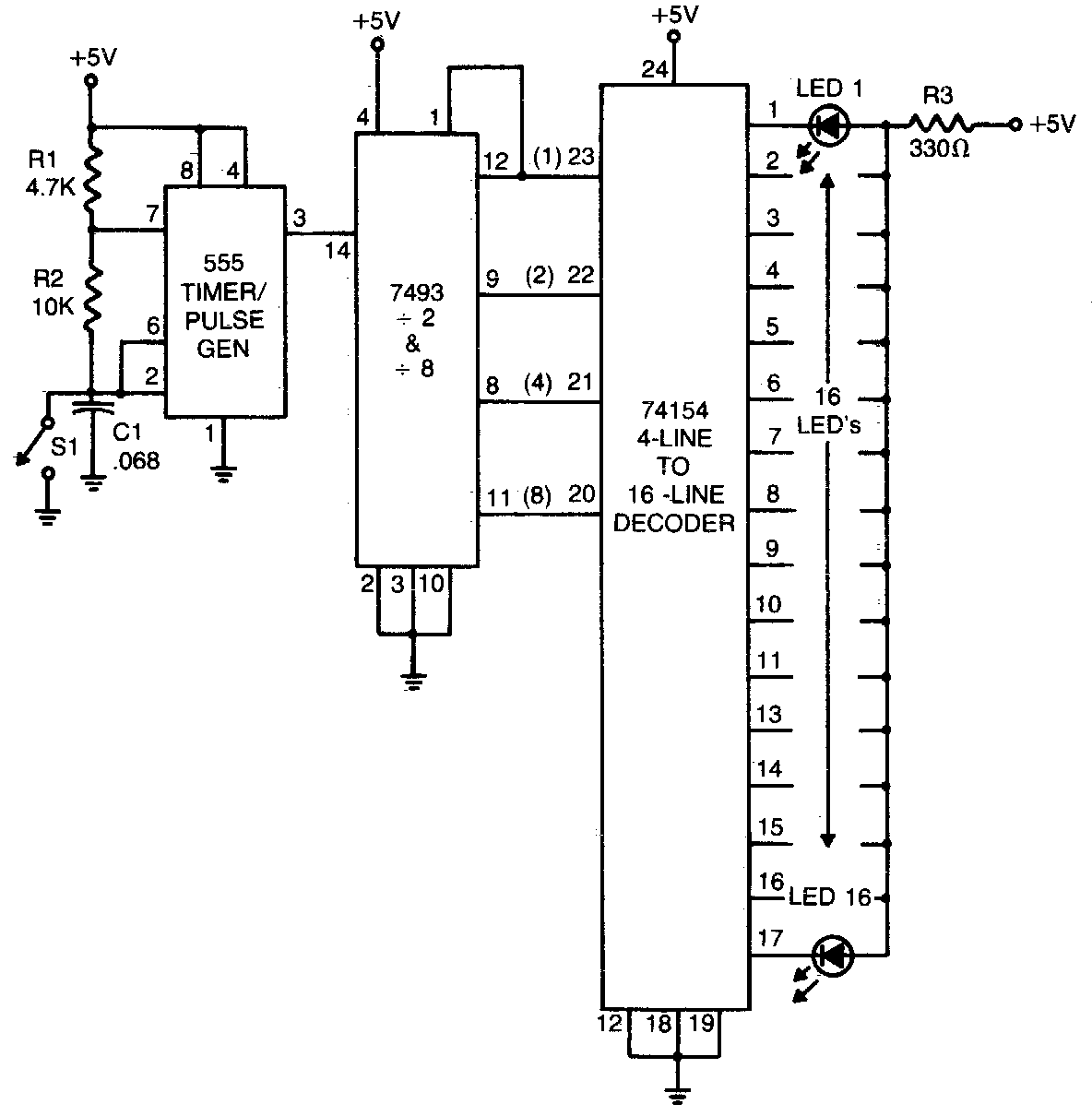
The 555 timer generates a rapid series of pulses when switch SI is open. These pulses are counted in groups of 16 and converted into binary form by the 7493, which is then fed into the 74154, a 1-of-16...
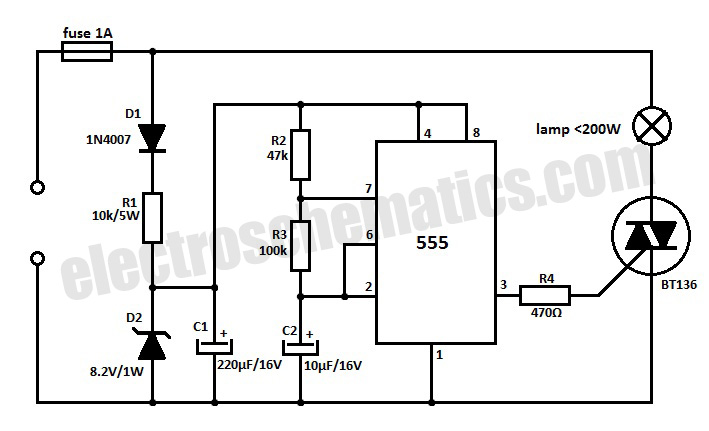
This 220V mains operated solid-state flashing lamp circuit utilizes a 555 timer integrated circuit (IC) to manage the ON and OFF durations of a triac that regulates power to the load. The circuit operates at a mains voltage of 220V,...
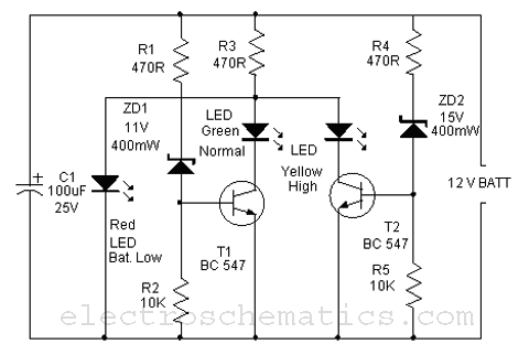
This is a simple battery monitor circuit designed for a quick assessment of a 12-volt lead-acid battery. Continuous monitoring of battery charge is essential to extend its lifespan. The battery monitor circuit typically consists of a voltage divider, an operational...