
C-Bot Article
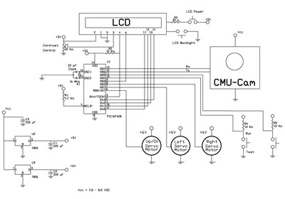
The schematic diagram presented in figure 10 outlines the connections and components necessary for constructing a functional circuit that incorporates a 2-line by 16-character LCD display. This display, compatible with the Hitachi 44780 controller, serves as the primary output interface for the circuit. The use of a breadboard allows for flexibility in prototyping, while a pre-manufactured PCB offers a more permanent solution for the assembly of the circuit.
The LCD module typically features a 14 or 16-pin configuration, which facilitates the connection to the microcontroller or other interfacing hardware. The pin assignments generally include data lines, control lines, and power connections. For optimal operation, it is essential to consult the specific datasheet for the LCD module being utilized, as pin configurations may vary slightly between different manufacturers.
To ensure proper communication between the circuit and the camera module, a jumper must be placed in position 2. This configuration is crucial for setting the camera's baud rate to 38,400 bps, which is a standard rate for serial communication in many electronic applications. The power supply connections are made at the designated header positions shown in figure 12, ensuring that both the LCD and the camera module receive adequate voltage and current for their operation.
Additionally, the schematic includes header positions for serial communication, specifically for transmitting and receiving data. These connections are vital for enabling the microcontroller to send commands to the camera and receive feedback or data from it. Proper attention to these connections will ensure reliable operation and communication within the system.The schematic is shown in figure 10. The circuit can be hardwire onto a breadboard or you can purchase a pc board, see figure 11. The LCD display used is a 2 line by 16 character display. You can use an LCD module with a Hitachi 44780 controller or equivalent. These LCD`s usually have a 14 or 16 pin header. Look at figure 12. Place a jumper on jum per position 2. This sets the camera baud rate to 38, 400. The power is supplied to the two header positions shown on figure 12, as well as the header positions for the serial transmit and receiver lines. 🔗 External reference
Related Circuits
The traffic light controller section consists of 12 point LEDs arranged in 4 lanes on the PS/8051 Trainer Kit. Each lane features a Go (Green), Listen (Yellow), and Stop (Red) LED. The PS-8051 board demonstrates the capabilities of the...
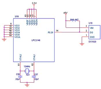
The PS-LPC2138 ADK, an ARM Development Kit, is designed to facilitate the development and debugging of various designs using a high-speed 32-bit microcontroller (MCU) from NXP. This board is compatible with the LPC214x family of devices and offers multiple...
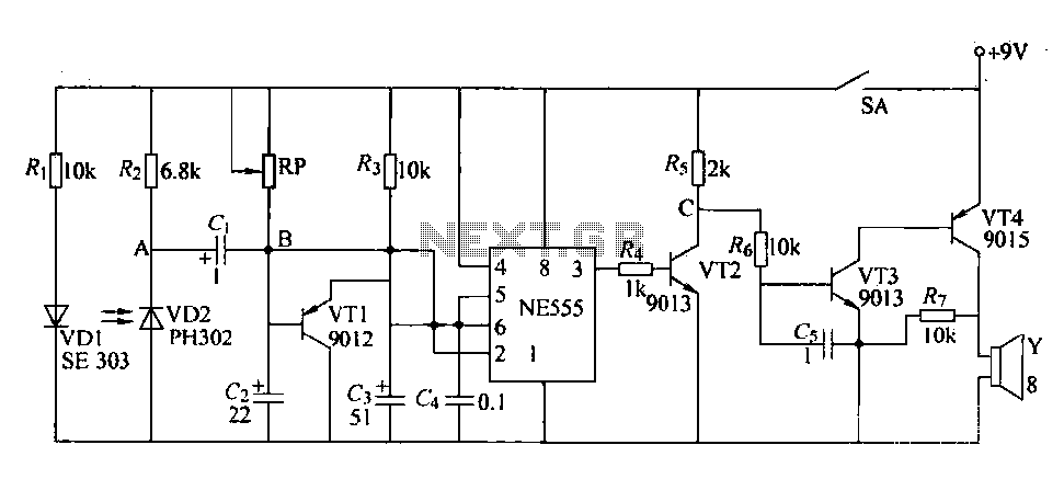
The circuit is designed to detect clogging in a wheat planter by utilizing light-emitting diodes (LEDs) and photodiodes. When the light path is obstructed by particles, the photodiode receives less light, causing the resistance of VD2 to increase. This...