
Cable TV Amplifier Using Transistors
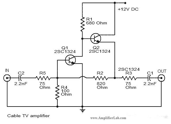
The cable TV amplifier circuit is designed to enhance the signal strength of cable television signals, improving the overall quality of reception. The primary components of this circuit are two transistors, Q1 and Q2, which serve as the main amplification elements.
Transistor Q1 is typically configured as a common-emitter amplifier, providing initial signal amplification. It receives the incoming weak signal from the cable line, which is coupled to its base terminal. The amplified output from Q1 is then fed into the base of transistor Q2. This second transistor is often configured to further amplify the signal, ensuring that the output is strong enough to drive the load, such as a television or set-top box.
Both transistors are biased correctly to operate in their active regions, allowing for linear amplification of the input signal. The circuit may also include passive components such as resistors for biasing, capacitors for coupling and decoupling, and possibly inductors for filtering purposes. These components work together to stabilize the circuit and reduce noise, ensuring a clean output signal.
Power supply considerations are critical for this amplifier circuit. Typically, a regulated DC voltage is used to power the transistors, which ensures consistent performance regardless of fluctuations in the supply voltage.
The output stage of the amplifier may incorporate additional components, like a matching network, to optimize the impedance for the connected load, further enhancing signal transfer and minimizing losses. Overall, this cable TV amplifier circuit is essential for improving the quality of cable television signals, making it a vital component in modern home entertainment systems.The circuit diagram of Cable TV amplifier has been published here. This cable TV amplifier circuit consists of two transistors Q1 and Q2. 🔗 External reference
Related Circuits
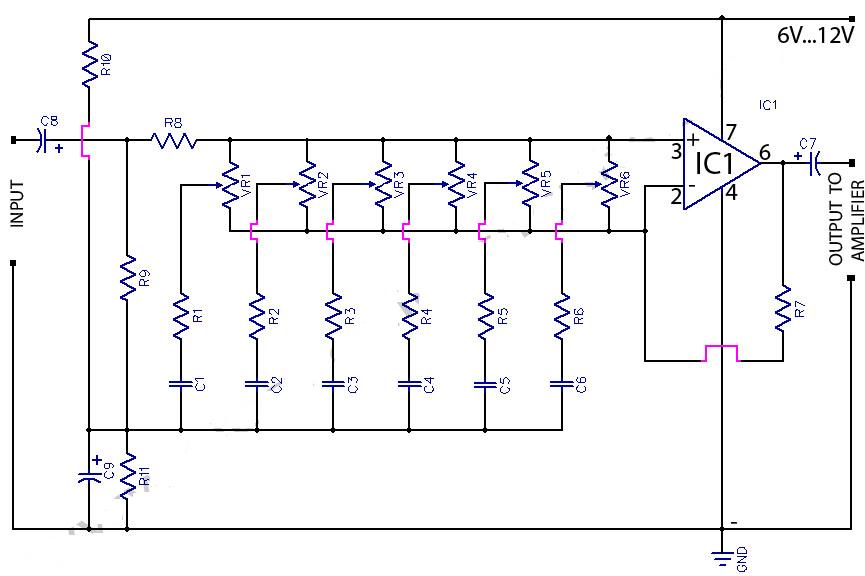
This circuit is a 6-band graphic equalizer that allows for the adjustment of low, medium, and high frequencies using the operational amplifier circuit 741. It enables control and mixing of frequencies and tones according to user preferences. The audible...
This month I am making 3 different types of siren circuits based on the 555 timer. The first circuit simulates the siren of a British police car. It uses two 555 timers in the circuit. The 555 on the...
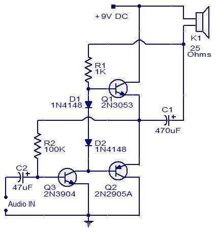
This circuit diagram illustrates a simple three-transistor audio amplifier capable of delivering approximately 100 mW of power to a 25 Ohm speaker. Diodes D1 and D2 provide a constant bias voltage for transistors Q1 and Q2. Transistor Q1 functions...
This circuit is a signal line so that you reinforce with a small speaker can control. The LM 386 is a number of versions available. LM 386N-1 can provide a power of 325 mW, the LM-386N 2500 mW, the...
Design and dimensioning of active low-pass and high-pass filters using Sallen-Key and multiple feedback topologies. Spice netlist generator. Active low-pass and high-pass filters are essential components in signal processing, allowing specific frequency ranges to pass while attenuating others. The Sallen-Key...
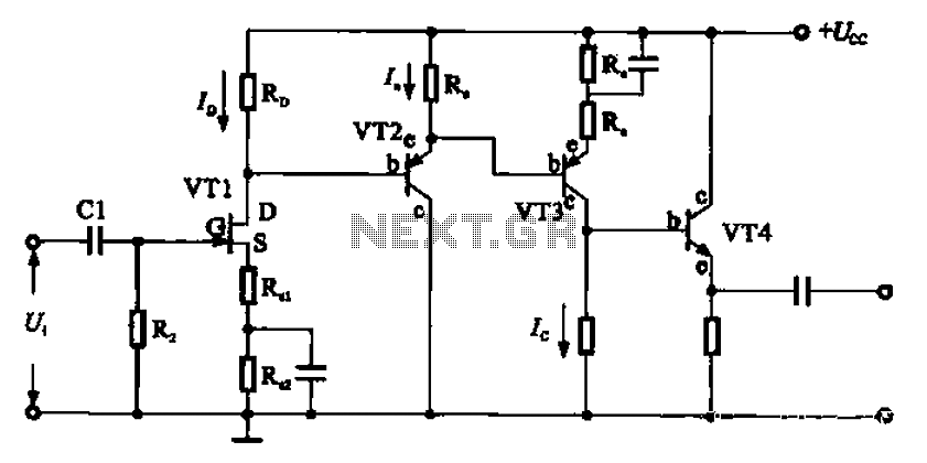
A combination of a common-source grounded emitter amplifier and a common emitter amplifier. The input impedance of the common emitter amplifier is in the range of 1.03 fl. Directly connecting the FET drive can be challenging; however, utilizing an...
Warning: include(partials/cookie-banner.php): Failed to open stream: Permission denied in /var/www/html/nextgr/view-circuit.php on line 713
Warning: include(): Failed opening 'partials/cookie-banner.php' for inclusion (include_path='.:/usr/share/php') in /var/www/html/nextgr/view-circuit.php on line 713