
Calibrated-tachometer
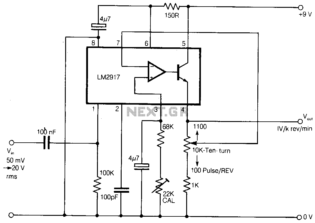
Here is a simple tachometer circuit for use with a hand-held DVM or portable chart recorder. A novel feature is that the source frequency pulse/rev rate can be directly set on a ten-turn potentiometer to provide a convenient calibration of one V per 1000 rev/min. This is particularly useful when measuring a shaft or engine speed by sensing gear teeth. The circuit uses an LM2917 IC which is specifically designed for tachometer applications. The ten-turn potentiometer, which provides the pulse/rev setting, is suitably configured in the output amplifier feedback path. The pulse/rev range is 100 to 1100, so the potentiometer dial mechanism should be set to start at 100 to provide direct calibration. The IC's internal 7.5-V zener provides stable operation from a 9-V battery. The tachometer accepts an input signal between 50 mV and 20 V rms and has an upper speed limit of 6000 rev/min with the component values shown.
The described tachometer circuit employs the LM2917 integrated circuit, which is tailored for frequency-to-voltage conversion, making it ideal for tachometer applications. The circuit's design allows for a straightforward calibration process, utilizing a ten-turn potentiometer that adjusts the pulse per revolution (pulse/rev) setting. This feature enables precise control over the output voltage, which is calibrated to produce one volt per 1000 revolutions per minute (rev/min).
The configuration of the potentiometer within the feedback path of the output amplifier is critical. It ensures that the output voltage scales accurately with the input frequency derived from the rotating shaft or engine. The specified pulse/rev range of 100 to 1100 indicates that the circuit can accommodate a variety of applications, from low-speed machinery to high-speed engines.
Powering the circuit with a 9-V battery is facilitated by the LM2917's internal 7.5-V zener diode, which stabilizes the operating voltage and enhances the reliability of the measurements. The input signal range of 50 mV to 20 V rms allows the tachometer to interface with a wide range of sensors, such as those detecting gear teeth or other rotational elements.
With a maximum measurable speed of 6000 rev/min, the circuit is suitable for numerous industrial and automotive applications. The careful selection of component values within the circuit is essential to maintain performance across the specified operational range, ensuring accurate and consistent tachometric readings.Here is a simple tachometer circuit for use with a hand-held DVM or portable chart recorder. A novel feature is that the source frequency pulse/rev rate can be directly set on a ten-turn potentiometer to provide a convenient calibration of one V per 1000 rev/min. This is particularly useful when measuring a shaft or engine speed by sensing gear teeth.
The circuit uses an LM2917 IC which is specifically designed for tachometer applications. The tenturn potentiometer, which provides the pulse/rev setting, is suitably configured in the output amplifier feedback path. The pulse/rev range is 100 to 1100, so the potentiometer dial mechanism should be set to start at 100 to provide direct calibration.
The IC"s internal 7.5-V zener provides stable operation from a 9-V battery. The tachometer accepts an input signal between 50 mv and 20 V rms and has an upper speed limit of 6000 rev/min with the component values shown.