
Camera-alarm-trigger
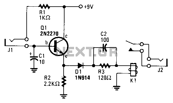
The transistor Q1 remains off until the magnetic switch connected to J1 closes. When this occurs, 9V is supplied through R1 to the base of Q1. As a result, Q1 turns on, which charges capacitor C2 through relay K1, causing the contacts of K1 to close. These contacts connect via J2 to the remote control jack in the camera, which in turn connects to the camera's shutter release. The closure of K1's contacts triggers the camera's shutter. Once C2 is charged, K1 opens because the current through its coil ceases, preventing the camera from taking another picture. If Q1 turns off due to the magnetic switch on the window or gate opening, C2 discharges, and the circuit is ready for another cycle. While Q1 is on, C2 remains charged, preventing K1 from triggering additional photos. Capacitor C1 bypasses spurious noises from the magnetic switch caused by physical phenomena, such as a rattling window or a shaking gate, thereby reducing the likelihood of an unwanted picture. Resistor R2 biases Q1 and dampens the oscillations of K1 and C2, which could lead to contact bounce. Diode D1 prevents C2 from discharging through K1; since the relay coil is not polarity conscious, discharging C2 through it would result in an unintended picture.
The circuit described utilizes a magnetic switch to control the operation of a transistor, which in turn activates a relay to trigger a camera shutter. The magnetic switch serves as an input mechanism, allowing the system to remain in a low-power state until the switch is closed, at which point the circuit is activated. The transistor Q1 acts as a switch that controls the flow of current to the relay K1. When the magnetic switch is closed, it provides a 9V signal through resistor R1 to the base of Q1, allowing it to conduct and enabling the charging of capacitor C2.
Capacitor C2 plays a crucial role in the timing of the circuit. Upon charging, it energizes relay K1, which closes its contacts and sends a signal to the camera's shutter release. This action captures an image. Once C2 is fully charged, the current flow through the relay coil stops, causing K1 to open and preventing further triggering of the camera until the circuit is reset.
The discharge of C2 occurs when the magnetic switch opens, allowing the circuit to reset for the next activation cycle. The presence of capacitor C1 is essential for filtering out noise that may inadvertently trigger the circuit. This capacitor helps to ensure that only significant changes in the magnetic field, such as those caused by an intentional opening of a window or gate, will activate the circuit.
Resistor R2 serves a dual purpose: it provides biasing for Q1, ensuring that it operates within its intended parameters, and it dampens any oscillations that may occur between the relay and capacitor, which could lead to contact bounce and multiple unintended triggers of the camera shutter.
Diode D1 is implemented to protect the circuit from potential back EMF generated by the relay coil when it is de-energized. This diode ensures that any discharge from C2 does not inadvertently flow back through K1, which could lead to false triggering of the camera shutter.
Overall, the design effectively combines various components to create a reliable and controlled mechanism for remotely triggering a camera shutter, while also incorporating safety features to minimize the risk of unwanted activations.Transistor Ql remains off until the magnetic switch connected to Jl closes. When that happens, the 9 Vis connected through Rl to Ql"S base. Ql turns on, thereby charging C2 through relay Kl, which causes Kl "s contacts to close. Since the contacts connect viaJ2 to the remote control jack in the camera, which in tum connects to the camera"s shutter release, the closure of Kl"s contacts will cause the camera"s shutter to trigger. After C2 charges, Kl opens because current through its coil ceases; the camera won"t take another picture.
If Ql turns off because the magnetic switch on the window or gate opens, C2 discharges and the circuit is ready for another cycle. As long as Ql remains on, C2 stays charged and prevents Kl from triggering more photos. Capacitor Cl bypasses spurious magnetic switch noises from physical phenomena, such as a rattling window or a gate shaking in the wind, thus reducing the likelihood of an unwanted picture.
Resistor R2 biases Ql and dampens Kl/C2 oscillations which might cause contact bounce. Diode Dl prevents C2 from discharging through Kl; the relay coil isn"t polarity conscious and C2 discharging through it would trigger an unwanted picture. 🔗 External reference