CAN Bus
4. Setting Up a Basic CAN Bus Network
4.1 Setting Up a Basic CAN Bus Network
Setting up a basic Controller Area Network (CAN Bus) involves careful planning of the physical layout, selection of components, and proper configuration of the software. The CAN protocol is well-suited for real-time communication across multiple devices, often utilized in automotive applications, industrial automation, and other fields requiring robust data exchange. This section will lead you through the essential steps to implement a working CAN Bus network.
Understanding the Components
Before proceeding with the setup, it's crucial to identify the necessary components that constitute a CAN Bus system:
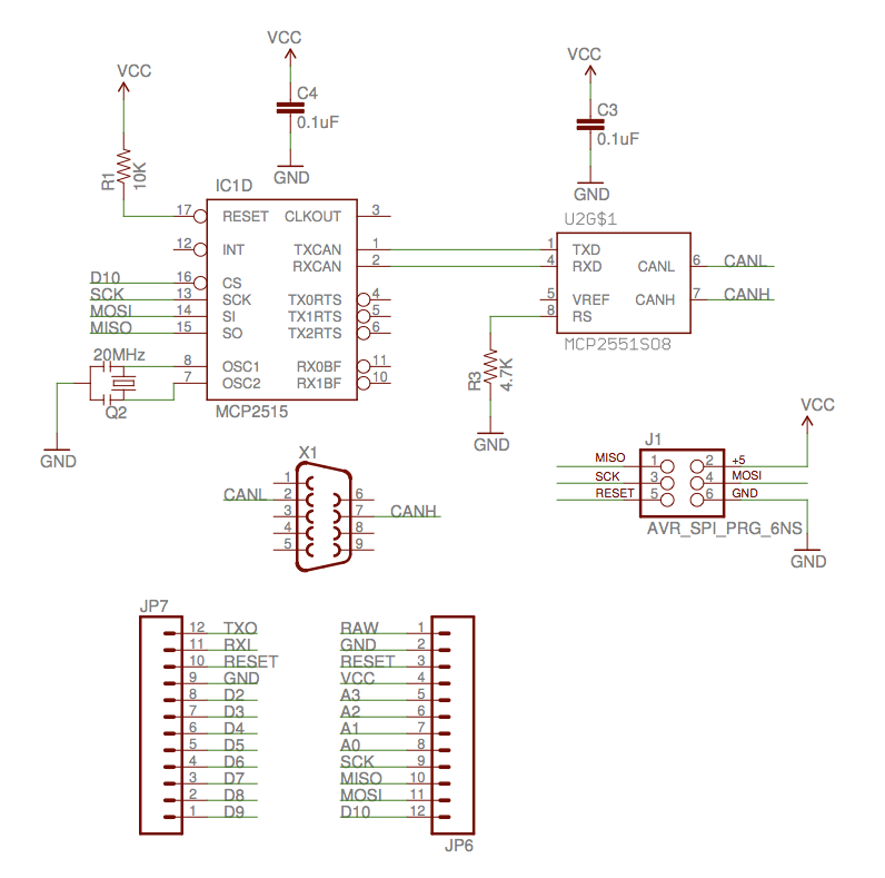
- CAN Controllers: These devices manage the CAN communication and can be integrated within microcontrollers or used as standalone chips like the MCP2515.
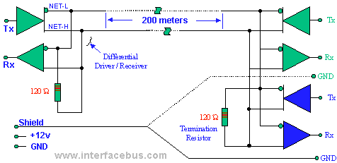
- Transceivers: Devices such as the TJA1050 convert the digital signals from the CAN controller into differential signals suitable for transmission across the network.
- Cabling: A twisted pair cable, preferably complying with ISO 11898, is commonly used to minimize electromagnetic interference and maintain signal integrity.
- Terminating Resistors: Two 120-ohm resistors are placed at both ends of the bus to prevent signal reflections, which can lead to data corruption.
- Microcontrollers: Many projects utilize microcontrollers with built-in CAN support, such as those from the STM32 or Microchip families.
Physical Setup
The physical arrangement of the components is instrumental for a reliable CAN Bus network. Follow these guidelines:
- The CAN network should be wired in a linear topology. This minimizes termination issues and optimizes the length of the bus.
- Ensure the total bus length does not exceed the specified limits (typically 40 meters at 1 Mbps), and observe the maximum connected devices (up to 110 nodes).
- Connect the transceivers to the buses through twisted pairs with minimal disruption, ensuring grounding is correct to avoid ground loops.
Software Configuration
Software configuration is typically performed in conjunction with embedded programming. Using a microcontroller, the CAN settings can be adjusted through its configuration register. For instance, the baud rate, filtering options, and interrupt settings must be defined based on the specifications of the devices included in your network. Below is a basic outline of how a typical initialization could look in a microcontroller's setup:
#include
#include

MCP_CAN CAN(10); // Set CS pin to 10

void setup() {
    Serial.begin(115200);
    if (CAN.begin(MCP_ANY, 500E3, MCP_8MHZ) == CAN_OK) {
        Serial.println("CAN Initialized");
    } else {
        Serial.println("CAN Init Failed");
    }
    CAN.setMode(MCP_NORMAL);
}

void loop() {
    // Your CAN communication code here
}
Testing the Setup
To ensure that your CAN Bus network is operational, implement a testing protocol:
- Use a CAN Bus analyzer tool to monitor the messages and diagnose potential issues.
- Verify the bus termination and cabling by checking signal integrity using an oscilloscope.
- Create simple send/receive tests between nodes to validate communication.
In conclusion, a robust CAN Bus setup is achieved by selecting appropriate components, establishing a reliable physical connection, and rigorously testing the configuration. This foundational understanding enables advancements to more sophisticated applications, such as implementing CANopen or DeviceNet protocols for complex environments.
4.2 Configuring CAN Devices
The Controller Area Network (CAN) Bus has become a fundamental cornerstone in automotive and industrial communication systems. Its robust nature, coupled with the ability to operate in real-time, allows for seamless inter-device communication. However, the performance and reliability of a CAN system significantly rely on proper configuration of the devices within the network. In this subsection, we will delve into the intricacies of configuring CAN devices, examining essential elements such as device addresses, baud rates, and filtering mechanisms.
Understanding Device Configuration
Each CAN device must have a unique identifier or address to distinguish itself from other devices on the network. This identifier is a crucial piece of data, especially when considering network efficiency and collision management. When configuring a CAN device, engineers typically design a systematic approach, which may involve the following steps:
- Choosing a Unique Identifier: In CAN, each message has an associated identifier which dictates its priority on the bus. Lower numerical values correspond to higher priority. Thus, selecting a unique identifier that aligns with the intended message priority can enhance network performance.
- Configuring Baud Rate: The baud rate determines the speed at which data is transmitted over the CAN bus. Common baud rates include 125 kbps, 250 kbps, 500 kbps, and 1 Mbps, depending on the application and cable length. It is critical for all devices in the network to operate at the same baud rate to ensure reliable communication.
- Setting Up Filtering Mechanisms: CAN allows for the configuration of message filters that can reduce unnecessary data traffic. By defining acceptance filters based on message IDs, devices can be programmed to ignore irrelevant data, optimizing performance and responsiveness.
Baud Rate Considerations
Configuring the baud rate involves selecting a value that balances data throughput with signal integrity over distances. The relationship between baud rate and cable length can be summarized in the following general guidelines:
- For short distances (under 40 meters), higher baud rates (up to 1 Mbps) can be utilized without significant signal degradation.
- For longer distances, one must reduce the baud rate to maintain stability, typically using lower rates like 125 kbps or 250 kbps.
This consideration is pivotal, as a too high baud rate may result in data loss due to reflections and attenuation on longer cables.
Addressing Modes: Standard vs. Extended
CAN messages can fall under two addressing modes: standard and extended. In standard mode, identifiers are 11 bits long, while in extended mode, they extend to 29 bits. The implications of this variability are significant:
- Standard CAN: This mode provides a simplified approach, suitable for most applications requiring fewer identifiers.
- Extended CAN: By enabling a larger identifier space, this mode is beneficial in complex systems where higher device counts and more message types are necessary.
When configuring a CAN device, it is essential to not only choose the appropriate addressing mode but also understand the implications for network load and message prioritization.
Practical Configuration: Case Study
To illustrate the practical nuances of CAN device configuration, we examine an automotive scenario involving multiple ECUs (Electronic Control Units) communicating through a CAN bus. In our case study:
- The Engine Control Unit (ECU) is given a high-priority identifier (0x100) to ensure timely processing of critical engine data.
- The Transmission Control Unit (TCU) follows with a moderately high identifier (0x200), which processes data from the ECU posthaste.
- Both devices are configured to mutually agree on a baud rate of 500 kbps, ensuring optimal data transfer rates.
This structured addressing not only ensures timely data handling but also enhances overall system efficiency and reliability.
where \( N \) is the number of nodes, and \( \text{Time}_{\text{bit}} \) is the time taken for each bit transmission. Understanding this formula aids in estimating the maximum latency based on the number of devices connected and the selected baud rate.
By effectively configuring CAN devices, engineers can ensure that communication remains efficient, responsive, and reliable. The culmination of proper addressing, baud rate management, and filtering mechanisms forms the bedrock of a successful CAN network configuration.
4.3 Tools for Monitoring and Diagnostics
The Controller Area Network (CAN Bus) has become a pivotal standard in vehicle and industrial communication systems. With its inherent robustness and flexibility, it is essential for engineers to employ precise tools for monitoring and diagnostics. The importance of implementing these tools extends beyond initial setup and debugging; they play a significant role in ensuring long-term system reliability and performance.
Within the realm of CAN Bus, various monitoring and diagnostic tools are available that cater to different needs and applications. These tools not only assist in identifying and rectifying faults but also provide insight into the operational performance of the network. In this subsection, we explore several leading tools and techniques used in the industry.
CAN Analyzers
CAN analyzers are specialized hardware or software tools that monitor the traffic on a CAN Bus. They capture and analyze data packets, allowing engineers to detect errors, diagnose faults, and ensure compliance with the CAN protocol. One of the most significant features of CAN analyzers is their ability to interpret the CAN messages in real-time.
Typical features of CAN analyzers include:
- Real-time monitoring: Enables continuous observation of CAN Bus traffic for quick diagnosis.
- Filtering capabilities: Allows users to filter messages based on identifiers or types, focusing on crucial transactions.
- Data logging: Maintains records of CAN messages over time for detailed post-analysis.
Examples of CAN Analyzers
Several commercial CAN analyzers are available on the market, such as:
- Kvaser Leaf: A versatile USB-to-CAN interface that supports multiple protocols and is widely used for its reliability.
- Peak System PCAN-USB: This tool provides extensive capabilities for monitoring and diagnosing CAN networks directly from a PC.
- Vector CANoe: A comprehensive software tool that not only analyzes CAN Bus traffic but also simulates and tests CAN systems in larger networks.
Diagnostic Protocols
Beyond the physical tools available, specialized diagnostic protocols enhance the monitoring capabilities of the CAN Bus. Protocols like On-Board Diagnostics (OBD-II) have been pivotal in automotive applications. OBD-II allows for the communication between the vehicle's onboard computer and external diagnostic tools, facilitating easy fault detection and management.
These protocols benefit from standardized codes (DTCs) that simplify troubleshooting by providing standardized error messages, making it easier for technicians to diagnose issues swiftly.
Common OBD-II Diagnostic Tools
- OBD-II Scanners: Handheld devices that connect to the vehicle’s diagnostic port to read codes and provide live data.
- Electronic Control Unit (ECU) Remappers: These tools aid in analyzing ECU data and can reprogram settings based on diagnostic findings.
Software Solutions
Throughout the industry, various software platforms exist that can interface with CAN Bus systems for both analytics and diagnostics. These platforms provide graphical user interfaces to visualize CAN Bus traffic, compare performance metrics, and generate reports.
Such software solutions often integrate algorithms for advanced data analysis, enabling predictive maintenance strategies to forewarn of potential system failures. This is practical in high-stakes environments where downtime can have critical consequences.
Notable Software Solutions
- CANalyzer by Vector: A powerful software tool for configuration and monitoring of CAN networks, known for its user-friendly interface.
- BusMaster: An open-source tool designed for the analysis of CAN communication, widely used in academic settings for research purposes.
In conclusion, monitoring and diagnostic tools for CAN Bus systems are indispensable for both real-time performance analysis and long-term maintenance. By leveraging CAN analyzers, diagnostic protocols, and sophisticated software solutions, engineers and technicians can ensure that their CAN systems operate efficiently and reliably, significantly impacting their applications across various industries, including automotive, industrial automation, and robotics.
5. Automotive Applications
5.1 Automotive Applications
The Controller Area Network (CAN) bus system has emerged as a cornerstone of modern automotive architecture, transforming vehicle dynamics and communication protocols. As vehicles evolve into high-tech devices increasingly reliant on various electronic control units (ECUs), their requirements necessitate robust, real-time communication networks. The CAN bus facilitates this by allowing multiple microcontroller and devices to communicate with one another without complex wiring harnesses. At the heart of the CAN bus system is its ability to ensure high reliability and fault tolerance, which are crucial in automotive applications. Every automotive network node can send and receive messages without needing a dedicated polling sequence. This characteristic is particularly beneficial in reducing the weight and complexity of wiring in contemporary vehicle designs, which can result in significant cost savings and simplified manufacturing processes. The practical implications of utilizing the CAN bus in automotive systems are profound. For instance, it enables seamless interaction between critical components such as the engine control unit (ECU), anti-lock braking system (ABS), airbag systems, and infotainment solutions. Each of these modules can prioritize messages based on their urgency, utilizing a priority-based scheme intrinsic to the CAN protocol where lower numerical identifiers take precedence. This eliminates the risk of critical data being overlooked due to less urgent signals. To understand the effectiveness of the CAN bus, it is vital to consider its message structure. Messages on the CAN network consist of an identifier, data payload, and a frame check sequence, which ensures integrity during transmission. The identifier not only distinguishes between messages but also implicitly conveys priority; a crucial feature when multiple ECUs might simultaneously attempt transmission. This method of prioritized communication helps maintain the vehicle's reliability in critical operations, such as emergency braking, where responsiveness is key. From a historical perspective, the CAN protocol was developed by Bosch in the 1980s, primarily to simplify communication within automobiles. Over the years, it has seen extensive adoption beyond automotive applications, including industrial automation and medical devices. However, its role in the automotive industry remains paramount; for example, the advent of electric and autonomous vehicles necessitates an even more sophisticated network of connectivity where the CAN bus acts as a foundation upon which advanced features such as autonomous driving can be built. In practical application, automotive engineers leverage the CAN bus for diagnostics and real-time performance monitoring. With the implementation of on-board diagnostics (OBD-II), technicians can access vital system and performance data via standardized CAN messages. This capability not only streamlines troubleshooting but also enhances overall vehicle safety and efficiency. As we look toward the future, the development of higher bandwidth versions of CAN, such as CAN FD (Flexible Data-rate), promises even more flexibility and capability, allowing for larger data frames and faster communication, essential for the burgeoning demands of modern automotive technologies. In summary, the CAN bus represents not just a communication protocol but a dynamic backbone for the modern vehicle's Electronic Control Unit architecture, paving the way for innovation in automotive design and functionality, while also holding significant implications for safety and performance.5.2 Industrial Automation
The Controller Area Network (CAN) bus has transformed the landscape of industrial automation, a field where reliability and efficiency are paramount. Originally developed for the automotive industry in the 1980s, the versatility of the CAN bus protocol has allowed it to permeate various sectors, integrating myriad components into cohesive, functional systems. This subsection delves into the application of CAN bus technology in industrial automation, highlighting its operational advantages, key features, and practical relevance.Key Features of the CAN Bus in Industrial Automation
The CAN bus boasts several features that make it particularly suitable for industrial applications:- Robustness: Designed to operate under electrically noisy environments, the CAN bus employs differential signaling to ensure reliable communication even amidst potential electromagnetic interference.
- Real-time performance: The protocol supports real-time data transmission, essential for systems requiring timely responses, such as in robotics and feedback control loops.
- Scalability: Systems can easily expand to incorporate multiple nodes without a complete redesign, allowing for the integration of additional sensors, actuators, and controllers seamlessly.
- Fault tolerance: The CAN bus includes mechanisms for error detection and fault confinement, ensuring that defective nodes do not compromise system integrity.
Applications of CAN Bus in Industrial Automation
CAN bus is widely adopted in various facets of industrial automation, including:- Manufacturing Systems: In smart factories, CAN bus connects programmable logic controllers (PLCs), robots, and sensor networks, facilitating efficient automation of production lines.
- Process Control: Systems in chemical plants utilize CAN bus for monitoring and controlling parameters such as temperature and pressure in real-time, thereby enhancing safety and optimizing production processes.
- Building Automation: Applications in HVAC (heating, ventilation, and air conditioning) systems leverage CAN bus to streamline operations, ensuring efficient energy use and improved comfort.
Implementation Considerations
While implementing a CAN bus system in an industrial automation setting involves various technical considerations, key aspects include: - Topology Design: The architecture of the CAN network—for instance, whether to use a star, ring, or line topology—significantly influences reliability and performance. The most common topology is the bus topology, where all nodes are connected to a single communication channel. - Data Rate Selection: The choice of data rates, which can range from 10 kbps to 1 Mbps, should align with the application's requirements for speed and distance. Higher rates may necessitate shorter cable lengths. - Node Configuration: Each device in the CAN network must be correctly configured, with unique identifiers ensuring that messages are correctly prioritized and routed. Real-world deployment of CAN bus systems illuminates these considerations, as companies have gleaned critical insights through iterative design and development processes.Future Directions and Innovations
As industries continue to evolve toward greater automation and connectivity, the CAN bus protocol is expected to adapt alongside emerging technologies. Innovations such as CAN FD (Flexible Data-Rate) significantly enhance transmission capabilities, allowing for larger payloads and quicker data transmission. This advancement is of particular relevance as systems increasingly demand higher efficiency and data throughput. Moreover, integration with Internet of Things (IoT) architectures is on the rise, with CAN bus forming a critical communication layer that supports both local and cloud-based data management solutions. In summary, the CAN bus remains a foundational technology in industrial automation. Its robustness, scalability, and versatile nature continue to drive productivity and innovation in various sectors, making it indispensable for modern industrial applications.5.3 Aerospace and Marine Systems
The Controller Area Network (CAN) Bus protocol is increasingly relevant in the context of aerospace and marine systems, where robustness and reliability are paramount. Both fields have unique challenges, such as high levels of electromagnetic interference (EMI), extreme temperature variations, and rigorous regulatory requirements. Fortunately, the CAN Bus, with its inherent features, is well-suited to address these challenges.
Understanding the Role of CAN Bus in Aerospace Systems
In aerospace applications, the CAN Bus is utilized predominantly for its fault-tolerant capabilities and real-time communication characteristics. For example, commercial aircraft systems leverage the CAN Bus to facilitate communication among various subsystems, such as engine management systems, flight control systems, and environmental control systems.
The architecture of a typical aerospace system could comprise multiple nodes, each responsible for specific tasks. These nodes communicate over a single twisted-pair cable that enhances data integrity and minimizes crosstalk. The maximum data transfer rate of CAN Bus can reach up to 1 Mbps, which is suitable for most aerospace sensor and control applications.
Real-World Applications in Aerospace
- The Boeing 787 uses CAN Bus for its Integrated Modular Avionics (IMA) system, where multiple functionalities are integrated into modular components, improving both efficiency and reliability.
- NASA's Mars Rover utilizes a form of CAN Bus to ensure communication among its various scientific instruments, providing resilience against the harsh environment of space.
Integration of CAN Bus in Marine Systems
Similarly, in marine applications, CAN Bus has gained traction to enhance communication between navigation systems, engine control units, and other critical components onboard vessels. The robustness of the CAN Bus protocol significantly reduces the risk of signal degradation caused by saltwater exposure or vibration.
Modern vessels such as container ships and luxury yachts incorporate CAN Bus networks to manage complex systems efficiently. One of its advantages is the distributed network structure, which allows for easy troubleshooting and flexible expansion of onboard systems without cumbersome rewiring.
Real-World Applications in Marine Systems
- Luxury yachts often deploy CAN Bus for systems such as power management, navigation, and engine control, which are integral to enhancing user experience and safety.
- Military vessels utilize CAN Bus to ensure secure and reliable communications in critical operations, including navigation and weapon systems control.
In conclusion, the adoption of CAN Bus in aerospace and marine environments demonstrates its versatility and effectiveness in addressing the specific requirements of these industries. With ongoing advancements in technology, the capabilities of the CAN Bus are expected to expand further, fostering innovation and enhancing operational efficiency.
6. Advancements in High-Speed CAN
6.1 Advancements in High-Speed CAN
The Controller Area Network (CAN) protocol has undergone significant evolution since its inception in the 1980s by Bosch. As vehicle electronics and sophisticated systems proliferate, the demand for faster and more reliable communication standards has driven the advancement of High-Speed CAN (HS-CAN)
At its core, HS-CAN was originally designed to address the limitations of traditional communication buses by providing a transmission speed of up to 1 Mbps. However, advancements in technology have led to the emergence of enhanced protocols that facilitate even faster data transmission and increased efficiency. This transition is particularly relevant within an expanding landscape of interconnected devices and systems where bandwidth is at a premium. One notable advancement is the development of CAN FD (Flexible Data-Rate), which allows for larger data payloads and improved efficiency. With CAN FD, the maximum data length per frame increases from 8 bytes to 64 bytes, allowing for more extensive information to be transmitted in each CAN message. This modification significantly impacts automotive design where sensors and control units increasingly rely on comprehensive data packets for real-time processing and decision-making. Additionally, CAN XL is on the horizon, promising speeds up to 10 Mbps and even larger data lengths. This leap is particularly notable in the context of applications requiring high data throughput, such as advanced driver-assistance systems (ADAS) and Vehicle-to-Everything (V2X) communication, where swift and reliable data sharing is crucial. With the increase in transmission speed, certain challenges emerge, such as electromagnetic interference (EMI) and signal integrity. The advancements in HS-CAN protocols also encompass robust error detection and correction mechanisms to confront these issues. The integration of mechanisms such as bit stuffing and CRC (Cyclic Redundancy Check) ensures the integrity of data as it traverses the bus. The continued research into physical layers, such as the adoption of twisted-pair cables and differential signaling, plays an essential role in mitigating EMI, enhancing the stability and reliability of high-speed transmissions. Practical applications of improved HS-CAN are evident in modern vehicles, where systems such as engine control units (ECUs), infotainment systems, and safety features necessitate the seamless operation of multiple nodes communicating simultaneously. Testing and validation become crucial in these environments, and simulation tools are now employed extensively to model the behavior of CAN networks under various conditions. In the automotive industry, ongoing experiments with HS-CAN implementations have demonstrated the protocol's capability to support innovative features, such as self-driving technology and enhanced connectivity. The future of HS-CAN lies in its potential integration with IoT (Internet of Things) infrastructures, promising a new level of interaction between vehicles and their environments. As advancements continue, the collaboration between automotive engineers, embedded systems developers, and network specialists will be pivotal in driving HS-CAN to meet the demands of the next generation of vehicles.Emerging Protocols and Their Applications
Challenges and Solutions in High-Speed CAN
Real-World Use Cases and Future Prospects
6.2 Integration with IoT
The integration of Controller Area Network (CAN) bus systems with the Internet of Things (IoT) is revolutionizing how devices communicate, particularly in automotive and industrial spaces. The primary strength of CAN bus lies in its robustness and efficiency—characteristics that complement the needs of IoT deployments where reliability and real-time data transmission are critical.
Understanding CAN Bus in a Networked Environment
At its core, the CAN bus protocol enables multiple microcontrollers to communicate with each other without a host computer. This decentralization is vital in IoT contexts where numerous devices often need to share data simultaneously.
When integrating CAN bus with IoT systems, devices equipped with CAN controllers can act as nodes in an IoT architecture. These nodes can send and receive signals, which can be processed to relay real-time information over the internet. This integration is typically achieved through gateways that translate CAN messages to a format suitable for transmission over IP networks, such as MQTT or HTTP.
Real-World Applications: Smart Cities and Industrial Automation
- Smart Cities: In smart city applications, CAN bus systems can monitor and control infrastructure such as traffic systems, environmental sensors, and public transportation, delivering data back to a central server for analysis and decision-making.
- Industrial Automation: Within industrial settings, CAN bus allows for control systems in manufacturing equipment to communicate effectively with cloud services, enabling predictive maintenance and real-time monitoring of machinery performance.
Emerging Protocols for Integration
Several protocols enable seamless integration of CAN bus with IoT applications. Notably, the ISO 15118 standard facilitates the communication between electric vehicles and charging stations, enhancing the functionalities of CAN bus by allowing direct internet connectivity. This opens the door for sophisticated energy management systems that optimize charging costs based on grid demands.
Challenges and Considerations
While the integration of CAN bus into IoT systems presents numerous advantages, it also brings challenges. Security is a major concern; as devices connect to the internet, they become vulnerable to cyber-attacks. Implementing robust encryption and secure communication protocols is essential to protect data integrity.
Another challenge involves interoperability between various communication protocols. As various manufacturers adopt CAN bus in their IoT devices, ensuring compatibility becomes crucial for widespread adoption.
Conclusion
The synergy between CAN bus technology and IoT is rapidly transforming industries by enabling smarter, more connected systems. As advancements in both fields continue, the potential applications are vast, ranging from enhanced automation processes to improved remote monitoring systems. Continuous research and development in security and interoperability will be vital in fully realizing this integration's capabilities.
6.3 Emerging Standards and Revisions
The Controller Area Network (CAN) Bus protocol, developed by Bosch in the 1980s, has seen a remarkable evolution since its inception. As the automotive and broader industrial sectors adopted CAN, the demand for enhancements in speed, functionality, and interoperability led to the development of emerging standards and revisions. These transactions reflect the growing complexity of system requirements and advanced communication architectures in contemporary applications.
Key Developments in CAN Standards
To meet evolving challenges, various adaptations of the original CAN standard have emerged. Notably, the release of CAN FD (Flexible Data-rate) in 2012 expanded the range of data transmission capabilities significantly.
- Increased Data Rate: In conventional CAN, the maximum data payload is limited to 8 bytes, transmitted at a maximum rate of 1 Mbps. However, CAN FD allows for a much larger data payload, up to 64 bytes, and enables transmission speeds exceeding 8 Mbps for the data phase of a message. This flexibility is crucial in applications needing greater data throughput, such as modern automotive systems that require high-resolution sensor data.
- Enhanced Efficiency: The arbitration phase remains unchanged, thus ensuring that legacy CAN systems can communicate seamlessly with CAN FD. This backward compatibility facilitates a smoother transition for industries upgrading their systems, maintaining existing investments while reaping the benefits of advanced capabilities.
ISO 11898 Revisions
The key standards governing CAN communication are specified under ISO 11898. Over the years, this standard has undergone revisions to maintain its relevance in real-world applications:
- ISO 11898-1: This segment specifies the data link layer and physical layer of transmission. The revisions have adapted the parameters for bus access, fault tolerance, and error management to enhance robustness and ensure reliability in different environments.
- ISO 11898-2: This part details the high-speed CAN functions, which has been critical for applications in harsh conditions like automotive environments. The updates have introduced new recommendations on electromagnetic compatibility (EMC) and improved resilience against noise and interference, crucial for maintaining communication integrity.
- ISO 11898-3: Focused on low-speed, fault-tolerant applications, this revision has optimized power consumption aspects, allowing devices to enter sleep modes effectively while maintaining communication capacity in safety-critical systems.
CAN in the Broader Context of Communication Protocols
Alongside the development of CAN FD and updates to the ISO standards, the landscape of communication protocols continues to diversify with technologies like Ethernet and LIN (Local Interconnect Network). The integration of CAN with these protocols often results in hybrid systems that can leverage the strengths of multiple methodologies.
For example, the combination of CAN with using Ethernet-based protocols allows for high-bandwidth applications while maintaining the deterministic characteristics of traditional CAN networks. Such hybridization is particularly evident in connected vehicles and smart manufacturing, where real-time data processing and communication are paramount.
Practical Applications and Future Directions
The emerging standards and revisions in the CAN Bus protocol are not merely theoretical; they bear considerable practical implications across various fields. Some notable applications include:
- Automotive Electronics: With growing demands for complex electronic control units (ECUs), CAN FD has become essential in facilitating data exchange among numerous ECUs, ensuring efficient operation and responsiveness in modern vehicles.
- Aerospace Systems: As aerospace systems increasingly adopt advanced computational technologies, enhanced CAN protocols ensure reliable communication in critical flight control systems.
- Industrial Automation: In manufacturing, the adaptability of CAN, through its revisions, provides a scalable solution for real-time monitoring and control across various processes.
As technology progresses, the CAN ecosystem will continue to evolve. The integration of newer methodologies, alongside the ongoing refinements of existing protocols, will ensure that the CAN Bus remains a vital component in the networking landscape of the future.
7. Academic Journals and Articles
7.1 Academic Journals and Articles
- ScienceDirect - CAN Bus Protocol — This article provides an in-depth analysis of the Controller Area Network (CAN) protocol, discussing its technical specifications and use cases in automotive applications.
- Development and Application of CAN-Bus Systems — A comprehensive study of how CAN-Bus systems are implemented and optimized for various industrial automation processes.
- IEEE Xplore - CAN Bus in Embedded Systems — This research paper examines the integration of CAN Bus in embedded systems, focusing on performance metrics and real-time applications.
- Springer - Global Positioning with CAN Bus — The article explores the synergy between CAN Bus and GPS technology in enhancing vehicle navigation systems.
- SAGE Journals - Security Aspect of CAN Bus — Discusses the vulnerabilities of CAN Bus in automotive networks and proposes security enhancements to protect against cyber threats.
- MDPI Sensors - Optimization of CAN Bus — Focuses on sensor integration and optimization techniques for improving data transmission efficiency in CAN Bus networks.
- arXiv - CAN Bus Diagnostics and Testing — A technical paper detailing diagnostic methods and testing frameworks for maintaining and troubleshooting CAN Bus systems.
- ACM Digital Library - Advances in CAN Protocol — This article provides insights into the latest advancements in CAN protocol, highlighting improvements in protocol efficiency and robustness.
- IEEE Xplore - Modeling CAN Bus Systems — Explores methodologies for modeling and simulating CAN Bus systems to predict performance and effect system design improvements.
7.2 Industry Standards and Specifications
Understanding the industry standards and specifications of the CAN Bus is crucial for engineers and researchers involved in automotive and industrial applications. The CAN protocol's robustness and reliability stem from these well-defined standards, ensuring compatibility and performance across different systems.Historical Context and Evolution
The CAN (Controller Area Network) was developed by Bosch in the 1980s to meet the growing need for robust data communication within motor vehicles. The formalization of standards such as ISO 11898 has been integral to its widespread adoption. Over time, several extensions and adaptations to the original protocol have been introduced, addressing diverse application needs and increasing system complexity.ISO 11898 Series
The ISO 11898 standard forms the backbone of the CAN Bus specifications. It has been subdivided into several parts, each dealing with different aspects of the communication protocol:- ISO 11898-1:2015 - This part specifies the data link layer, including message framing, arbitration, acknowledgment, and error detection. The message priority is handled by a non-destructive bit-wise arbitration mechanism.
- ISO 11898-2:2016 - Covers the high-speed medium access unit, defining electrical characteristics that support bit rates up to 1 Mbit/s. It details the physical layer's requirements, ensuring robust communication over twisted-pair cables.
- ISO 11898-3:2006 - Describes the low-speed fault-tolerant CAN, designed for systems where data rates up to 125 kbit/s are sufficient. This standard emphasizes fault tolerance and extends the reach of the CAN network.
- ISO 11898-4:2004 - Introduces time-triggered communication for improved determinism in data transmission, which is critical in real-time systems.
High-Level Data Link Control (HDLC)
CAN protocol integrates concepts from HDLC (High-Level Data Link Control), particularly in adopting crucial error-detection and acknowledgment procedures. This adaptation has fortified CAN systems against data corruption and synchronization issues, ensuring reliable inter-node communication in vehicular networks.Bit Timing and Synchronization
Bit timing in CAN is a complex procedure that allows synchronization of nodes on the network. This is crucial for maintaining data integrity and avoiding collisions. Bit timing is split into four segments: synchronization, propagation, phase buffer segment 1, and phase buffer segment 2. Adjustments based on monitoring the signal edges allow for dynamic synchronization across different nodes.CAN FD (Flexible Data Rate)
Introduced by Bosch in 2012, CAN FD enhances the original protocol by allowing flexible data rates, extending the data field up to 64 bytes per frame, significantly increasing throughput. This development responds to the growing demands for higher data volume and speed in applications such as ADAS (Advanced Driver Assistance Systems).Practical Applications and Real-World Relevance
CAN Bus industry standards enable reliable communication in a variety of sectors beyond automotive, including industrial automation, aerospace, and medical equipment. These standards ensure interoperability, facilitating integration across different networks and devices. The insights provided by ISO guidelines help designers make informed decisions, optimizing topology and fault-tolerant strategies to suit specific applications. In summary, mastering CAN Bus standards and specifications empowers engineers to design resilient communication systems that meet the high demands of modern technology environments. The standards not only guide development but also ensure reliability, adaptability, and success in deploying effective communication networks.7.3 Recommended Books and Online Resources
- Automotive Ethernet - The Definitive Guide — This book by Bob Metcalfe provides a comprehensive exploration of Ethernet innovations and applications in the automotive industry, including the use of CAN Bus.
- Controller Area Network — This resource provides in-depth coverage of CAN Bus, its protocols, and implementation techniques, catered towards engineers and researchers.
- CAN for Beginners — This online article simplifies the complexities behind CAN Bus technology for advanced learners by offering tutorials on basic principles and their real-world applications.
- The CAN Book — Authored by Wilm Tyl, this book is an authoritative guide on using CAN technology in various industries, including transportation and industrial settings.
- Vector CAN Solutions — Vector offers a suite of software tools and comprehensive documentation for simulation, testing, and analysis of CAN Bus systems.
- Copperhill Technologies - CAN Bus Technical Documents — A collection of technical papers, application notes, and detailed guides on implementing and troubleshooting CAN Bus systems for engineers.
- From CAN to CAN FD - Free eLearning Course — An advanced eLearning course offered by Vector, exploring the evolution from CAN to CAN FD, and practical considerations for transitioning systems.
- Microchip Developer: CAN Introduction — This portal provides detailed articles and tutorials on the technical foundations and modern advancements in CAN Bus technology.