
Capacitance Meter ( 68HC711D3FN )
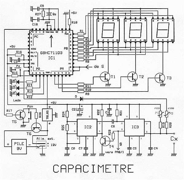
Component List
1 68HC711D3FN programmed
2555 CMOS
1 78L05
T1 .. T5 BC549B
T6 BC559B
D 1N4148
3 LED 3mm red
R1 .. 8390 Ω
R9 .. 11, R26 3.9 kΩ
R12 .. 14 470 Ω
R15, 17, 18 18 kΩ
C1, C3 100 nF LCC
R16 47 kΩ
C2 22 µF 16V Tantalum Bead
R19 820 kΩ
C4 270 pF styroflex
R20 560 Ω
C5, C7 10 nF LCC
R21, R23 10 kΩ
R22 2.7 kΩ
R24 820 kΩ
R25 100 kΩ
P1 220 kΩ adjusted T93YA
R27 10 MΩ CMS 1206
P2 220 Ω adjusted T93YA
A printed circuit board includes:
1 BR 2 44 PLCC socket banana jack 2mm (blue, yellow)
3 displays a connector OPAFFCC ALE120
An 8 MHz quartz a 9V battery connector
2 BR 2 DIL sockets 8 round keys D6 (CORD6V, CORD6J)
30 spikes tulip (6 x 5) 1 box HAED2006M cut
MOUNTING
The assembly should be performed in the following order:
1. Install resistors R1 to R26.
2. Mount the two straps of the 555 timers.
3. Attach the pins for the tulip displays.
4. Insert the PLCC socket in the correct orientation.
5. Install both DIL sockets.
6. Connect capacitors C1 to C8.
7. Place transistors T1 to T6 and the diode D.
8. Solder the battery connector to the back.
9. Attach the external power supply connector.
10. Position the buttons and LED diodes, ensuring they protrude slightly and are mounted at the correct height.
11. Finish by soldering the 3 CMS components: C9, C10, R27, and finally the quartz.
COMMISSIONING
Before inserting IC1 to IC3, power up the circuit and verify that +5V is present where expected. If an oscilloscope is available, install IC2 and IC3 and check for a positive pulse of approximately 270 µs on pin 3 of IC3. Install IC1 in the correct orientation and power on. The display should quickly show a value of 0 pF with the pF LED illuminated. If the display does not indicate this, power down and check the connections.
CALIBRATION
Connect a capacitor with a known value of approximately 680 nF and adjust P1 to display this value. Then connect a capacitor greater than 1 µF (for example, two 680 pF capacitors in parallel) and adjust P2 to display this value. The operation of this capacitance measurement is automatic; simply apply power, connect the capacitor to be measured (ensure it is not charged) to the Cx input, and read the results. It is crucial to connect electrolytic capacitors in the correct polarity. If a capacitor exhibits abnormal leakage, measurement will be impossible due to the inability to charge. The Pz button allows for manual resetting to "0" if necessary, which is useful when measuring capacitors soldered to the end of a shielded wire. In this scenario, perform the zeroing with the cable connected, then attach the capacitor, and repeat the zeroing if the cable is removed. For measuring CMS 1206 and 805 packages, it is recommended to create a special interim connection.The proposed capacitance is a very powerful assembly to measure in 7 ranges capacitors of 1 pF to 999 uF, avecune excellent precision of about 10 -3 . The range change is fully automatic. The display shows 3 digits with decimal point. Three LEDs indicate the unit: pF nF uF or. Power is normally with a battery or 9V battery with automatic shutoff after 2.5 minutes. A jack for external power supply is also planned. The capacitor Cx to be measured determines the RC time constant of a monostable built IC3, a 555 Cmos (t = RC) And a capacitor of 1 nF and a load resistor (R19 + P1) 1 M W , give a pulse of t = 10 6 x 1.10 -9 = 10 -3 s = 1 ms = 1000 microseconds. This impulse appears in S and is measured by IC1 in mu.s, which gives a result equal to 1000 posted on 3 digits as "1.00 nF" Monostable IC3 is triggered periodically by the astable oscillator IC2, a 555 also.
The transistor T4 requires a reset of IC2 as the impetus created by IC3 is not over. The mu.P IC1 measure the duration of the pulse, manages the display of 3-digit multiplexed, determines Three most significant digits to display, remove leading zeros, place the decimal point. It also ensures the switching of the load resistance The first 4 lines are with R19 + P1 giving a value ranging pF or nF until 983 nF.
In addition, R20 + P2 are connected in parallel so as to have a speed of load 1000 times to go up 999 uF The 270-pF capacitor C4 is permanently connected to the measuring input. It allows a minimum pulse measured by the system. Pz pusher allows for the offset of that value and then display "0 pF. Note that, powering the "zero" is done automatically. Powering internal battery is by a short press Pon making T6 driver. The program starts and then passed to a PC3 So T5 driver: The pusher may then be released. 2.5 minutes later, PC3 falls to 0 keeping the capacitance at rest. The auto-off feature does not exist in the case of external power. Component List 1 68HC711D3FN programmed 2555 CMOS 1 78L05 T1 .. T5 BC549B T6 BC559B D 1N4148 3 LED 3mm red view of completed unit R1 ..
8390 W R9 .. 11, R26 3.9 k W R12 .. 14 470 W R15, 17,18 18 k W C1, C3 100 nF LCC R16 47 k W C2 22 uF 16V Tantalum Bead R19 820 k W C4 270 pF styroflex R20 560 W C5, 7 10nF LCC R21, 23 10k W C6 470 pF cér/5mm R22 2.7 k W 1 uF C8 LCC R24 820 k W C9, 27 October 1206 pF SMT R25 100 k W P1 220 k W adjusted T93YA R27 10 M W CMS 1206 P2 220 W adjusted T93YA A printed circuit 1 br 2 44 PLCC socket banana jack 2mm (blue, yellow) 3 displays a connector OPAFFCC ALE120 An 8 MHz quartz a 9V battery connector 2 br 2 DIL sockets 8 round keys D6 (CORD6V, CORD6J) 30 spikes tulip (6 x 5) 1 box HAED2006M cut MOUNTING You can follow the following order: The resistors R1 to R26 The two straps of the 555 The pins enhances tulip displays The PLCC socket in the right direction Both DIL sockets The capacitors C1 to C8 The transistors T1 to T6 and the diode D The battery connector, welded to back son The external power supply connector To place the buttons and LED diodes, we recommend using the front panel case thereby to protrude slightly and keys to mount the diodes at the right height Finish by soldering the 3 CMS back: C9, C10, R27 and finally the quartz COMMISSIONING Before placing IC1 to IC3, power up and check that the + 5V exists and where it should happen! If you have an oscilloscope, place IC2 and IC3 and verify the presence IC3 pin 3 of a positive pulse of about 270 ?S Install now IC1 in the right direction ...
and turn it on. Displays shall quickly indicate a value of 0 pF "with LED lights pF. Otherwise cut quickly and CHECK! If you have a 0, all is well! CALIBRATION Connect a capacitor of 680 nF approximately known values. Set P1 to display this value. Connect a capacitor of more than 1 uF and value KNOWN (Eg two 680 pF in parallel). Set P2 to display this value. The operation of this capacitance is automatic, there is not much to say! ! Apply power, connect the capacitor to be measured (NO CHARGE) on the entry Cx. Read the results! ! Be sure to connect the chemical in the right direction. Note that if a capacitor "leaks" abnormally, the measurement is impossible, the burden can not be done. Pz button allows the rebuild manually "0" if necessary. It is useful if you want to measure capacitor by welding to the end of a shielded wire. In this case, do the 0 with the cable, then connect the capacitor. Repeat 0 if you remove the cable. For measurement of CMS 1206 and 805, we recommend making a special interim. 🔗 External reference
Related Circuits
This FET voltmeter (FETVM) serves as a replacement for the vacuum tube voltmeter (VTVM) and eliminates the need for a standard line cord. Additionally, the drift rates of field-effect transistors (FETs) are significantly better than those of vacuum tube...
The Model LM-13 Crystal Calibrated Frequency Indicating Equipment has been specifically designed to provide a simple, accurate, and reliable frequency indication for the crystal calibrated type, intended for use in the U.S. Naval radio service. It is adaptable for...
Some experts believe that static magnetic fields (SMFs) may affect the physical well-being of individuals. If one subscribes to this viewpoint, the magnetic-field meter described here will aid in locating sources of SMFs and assessing their strength. These results...
A 0 to 2 MHz frequency meter with a Minimum Mass Wireless Coupler, based on the ATMega8. Range to the Minimum Mass Base Unit is 10 to 15 cm. Since the frequency meter is battery operated, it can be...

The magnetometer was relocated to an outdoor site, and a specialized enclosure was constructed. An accessory temperature controller was incorporated to ensure a constant temperature, and a digital link was established to transmit the recorded data back to the...
The circuit for the Digital Tachometer/RPM Counter consists of only a few devices. Wire them up according to the following circuit diagram. The PIC used is on a demonstration board, which means the clock, power, and ground pins are...