
Capacitance Meter Circuit
A capacitance meter is a specialized device designed to measure the capacitance of capacitors in various electronic circuits. It typically features a digital or analog display that indicates the capacitance value in microfarads (µF), nanofarads (nF), or picofarads (pF). The operation of a capacitance meter is based on the principle of charging and discharging a capacitor through a known resistor, allowing the meter to calculate the capacitance based on the time constant of the RC circuit.
In a typical capacitance meter circuit, a microcontroller or dedicated IC is employed to control the measurement process. The circuit includes a power supply, often powered by batteries or an external source, and an input terminal where the capacitor to be tested is connected. The meter may also incorporate a range switch to select different measurement ranges, enhancing its versatility for various capacitor types.
The measurement process begins when the user connects the capacitor to the input terminals. The meter applies a voltage to charge the capacitor and monitors the time it takes for the capacitor to reach a predefined voltage level. This time measurement is then processed by the microcontroller, which calculates the capacitance value using the formula derived from the time constant of the RC circuit.
Advanced capacitance meters may offer additional features such as automatic range selection, tolerance measurement, and the ability to test capacitors in-circuit, which can be particularly useful for troubleshooting electronic devices. Some models may also provide a continuity test function, allowing the user to check for short circuits or open connections in components.
Overall, a capacitance meter is an invaluable tool for anyone working with electronic components, providing accurate measurements that are critical for circuit design, repair, and maintenance.Capacitance meter is one instrument that you should have in your toolbox if you are an electronics hobbyist, or if you`re a professional electronic technician . 🔗 External reference
Related Circuits
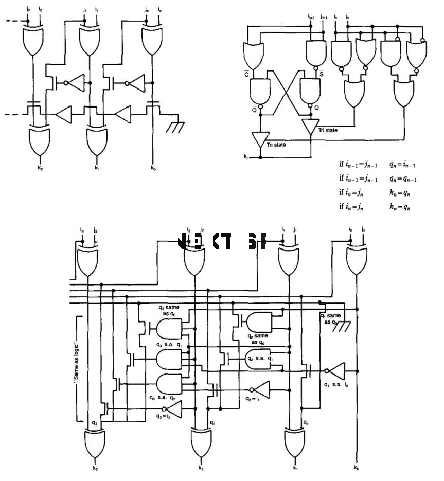
Some circuits that add binary numbers experience time delays due to carry propagation. This issue has been partially addressed by the carry look-ahead adder. However, the complexity of this method typically limits its application to no more than 4...
Modify it to click and latch a relay when the button is pressed from anywhere in the house. Additionally, if possible, unlatch the relay when pressed again. A flip-flop circuit may be created to take the first signal and...
A DIY GSM jammer schematic diagram designed specifically for GSM1900 frequencies ranging from 1930 MHz to 1990 MHz. The GSM1900 mobile phone network is utilized in the USA, Canada, and most South American countries. This cell phone jammer is...
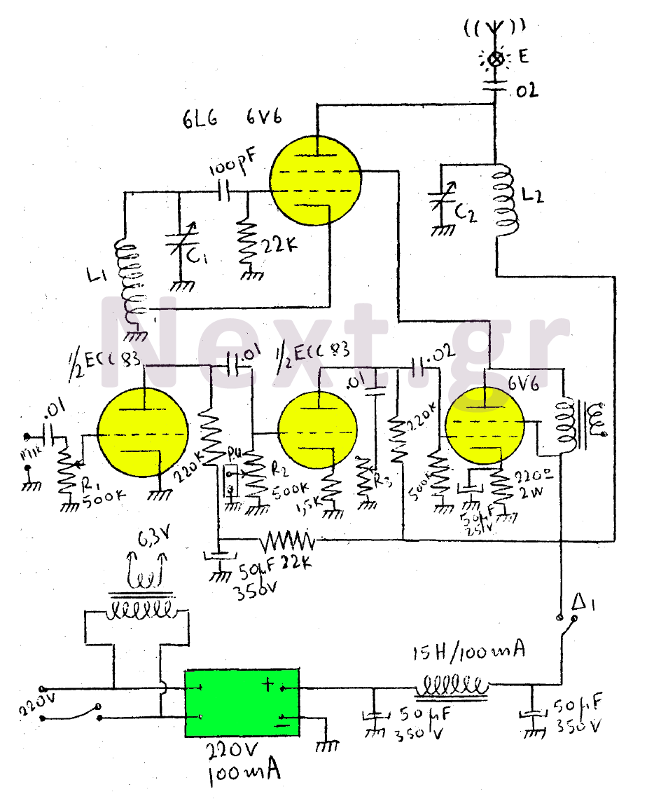
This circuit features a wearer assembly that includes a single lamp, either a 6V6 or 6L6, functioning as both an oscillator and an output amplifier. Coil L1 serves as the medium wave oscillation coil, while coil L2 is composed...
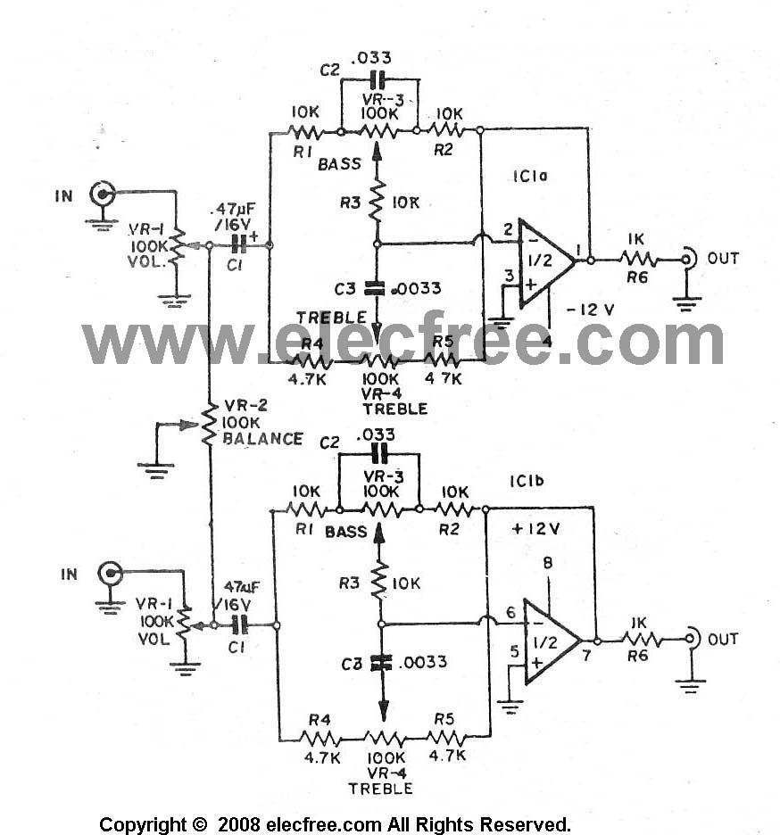
A high-quality preamplifier with tone controls consisting of three circuits. The NE5532 is chosen as the main integrated circuit due to its ultra-low noise properties, making it a popular choice in fine audio applications. Although these circuits are older...
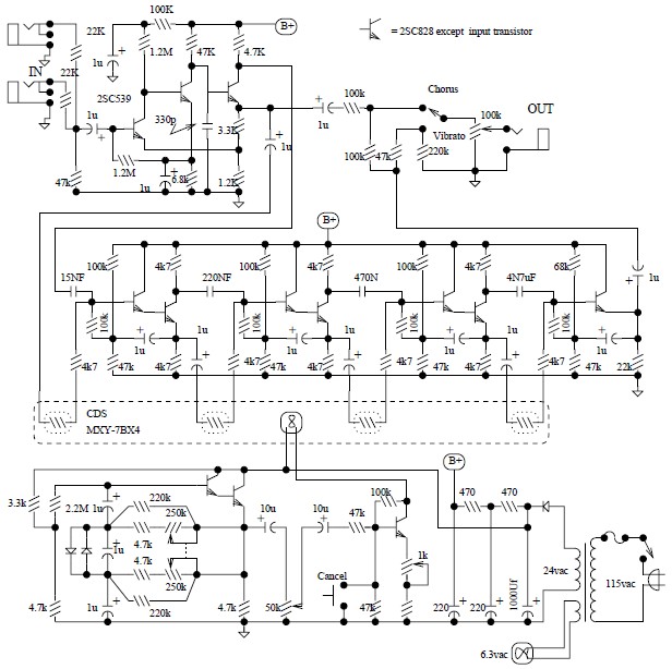
The Univibe is a footpedal-operated phaser or phase shifter designed to generate chorus and vibrato simulations for electric organs or guitars. It was introduced in the 1960s by Shin-ei, with the intention of emulating the "Doppler sound" characteristic of...
Warning: include(partials/cookie-banner.php): Failed to open stream: Permission denied in /var/www/html/nextgr/view-circuit.php on line 713
Warning: include(): Failed opening 'partials/cookie-banner.php' for inclusion (include_path='.:/usr/share/php') in /var/www/html/nextgr/view-circuit.php on line 713