
Car audio amplifier
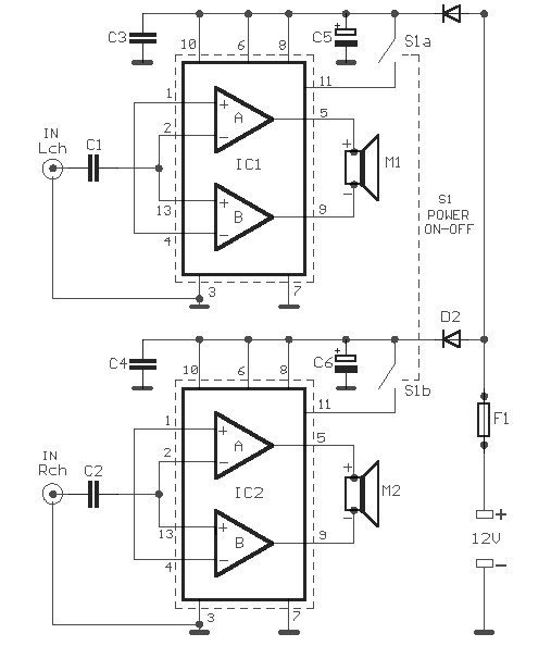
The car audio amplifier circuit utilizes a dual amplifier configuration to enhance audio output effectively. The TDA2004 integrated circuit serves as the core of the amplifier, providing a robust platform for audio amplification. It is designed to operate with a supply voltage of +12 V, which is standard in automotive applications.
In a bridge configuration, two TDA2004 amplifiers are employed, allowing for increased output power. This setup effectively doubles the voltage swing across the speaker, leading to a theoretical output power of 40 watts. However, practical limitations, such as thermal dissipation and speaker impedance, may result in a maximum achievable output of around 20 watts.
The input stage of the circuit is connected to the output of the car's audio receiver, which provides the audio signal to be amplified. The output of the TDA2004 is then connected directly to the speaker. It is essential to ensure that the speaker is isolated from the vehicle's chassis ground to prevent potential damage to the amplifier. This isolation can be achieved by using isolated speaker terminals or employing a transformer to decouple the speaker from the ground.
Additionally, the circuit should include appropriate filtering capacitors at the power supply pins of the TDA2004 to ensure stable operation and minimize noise. Bypass capacitors close to the power supply pins can help in reducing high-frequency noise, ensuring a clean audio output.
In summary, this car audio amplifier circuit is a practical solution for enhancing the audio experience in a vehicle, providing a significant increase in output power while maintaining the integrity of the audio signal. Proper implementation of the circuit, along with attention to grounding and power supply decoupling, will yield optimal performance.Car audio amplifier schematic diagram. Given the voltage of the car is +12 V, we have the opportunity to take power over a threshold. The solution is to use two amplifiers in bridge connection, so the output quadrupled, at least theoretically, and at best, doubled. This 20w car audio amplifier circuit described hereoffers a20 wattboosterthatwillal low youtorealize thepower amplifierwith which one canincrease the poweroutputfromthe carstereoup to20Wattsmaximum. The inputINis connected to theoutputof thereceiver, Uoutputis connectedto the speakeras shownoncaraudioamplifierscheme.
It is veryimportanttoensurethat thespeakerhas no connection tothe chassis(ground)ifnot, the integrated circuitIC1, aTDA2004will. 🔗 External reference
Related Circuits

The AC negative feedback circuit consists of resistors R and R, as illustrated in Figure 1-30. In this configuration, capacitor C3 can be treated as a short circuit. The actual results are depicted in Figure 1-32. An AC voltage...
Most universal radio receivers have a very wide bandwidth that is not particularly suitable for radio amateurs. The better models with narrower bandwidth are almost a... Universal radio receivers are designed to operate over a broad frequency range, making them...
The circuit utilizes a thermistor and three sections of a LM3900 quad operational amplifier (op amp) integrated circuit. When the temperature decreases to 36°F, an LED indicator flashes approximately once per second. As the temperature continues to drop to...
The circuit is a microphone amplifier for use with low impedance (~200 ohm) microphones. It will work with stabilized voltages between 6-30VDC. If you don`t build the impedance adapter part with T1, you get a micamp for higher impedance...
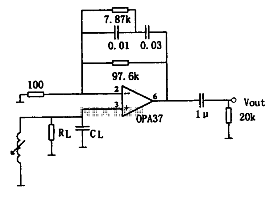
The OPA37 serves as a low-noise preamplifier. The input signal is connected to the inverting input of the OPA37 (pin 3), while the circuit components RL and CL represent the load impedance for electromagnetic pickups. The resistance and capacitance...
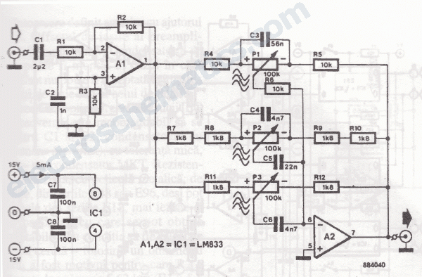
The primary component of this three-band graphic equalizer is the LM833, manufactured by National Semiconductor. The LM833 features very low noise levels and operates with a bandwidth of 15 MHz. The LM833 operational amplifier is designed to provide high-performance audio...
Warning: include(partials/cookie-banner.php): Failed to open stream: Permission denied in /var/www/html/nextgr/view-circuit.php on line 713
Warning: include(): Failed opening 'partials/cookie-banner.php' for inclusion (include_path='.:/usr/share/php') in /var/www/html/nextgr/view-circuit.php on line 713