
Car battery Indicator (BC548)
The described circuit serves as a battery voltage monitoring system, utilizing three different colored LEDs to indicate the state of the battery. The circuit operates within a voltage range of 9 to 14V DC and consumes a current of approximately 40 mA.
The first LED, labeled D1, is a red LED that functions as a low voltage indicator. It is connected in series with a 470-ohm resistor (R2) and a diode (D4) to prevent reverse polarity. When the battery voltage drops below 12V, D1 will illuminate, signaling that the battery voltage is insufficient.
As the voltage rises above 12V, a zener diode (Z3) rated at 11V and a resistor (R5) work together to activate the first NPN transistor (TR1, BC548). When TR1 is turned on due to the higher voltage, it allows current to flow to the second LED (D2), which is green. This LED indicates that the battery voltage is within the acceptable range of 12V to 13.8V, indicating a healthy battery condition.
If the battery voltage exceeds 13.5V, the circuit activates a second NPN transistor (TR2, also a BC548). This transistor controls the third LED (D3), which serves as an overvoltage indicator. The increase in voltage is detected through a pair of zener diodes (Z1 and Z2, both rated at 6.8V) and a resistor (R3, 100 ohms). When the voltage exceeds the threshold, D3 will light up, indicating that the battery is overcharged and may require attention.
In summary, the circuit efficiently monitors battery voltage levels and provides visual feedback through three LEDs, each corresponding to different voltage ranges: red for low voltage, green for normal voltage, and amber for overvoltage. This allows for easy assessment of battery health and management.The operating principle of the circuit is very simple. The first Led D1 is placed in series with the resistor R2 and diode D4.An only be lit this LED indicates that the battery is ypofortismeni. For this reason Led D1 is red. If the voltage is greater than 12V, then netting R5 Z3 turns the transistor TR1, so the glows and Led D2 indicates that the battery of your car is okay and that is why color is green.
Now, if the battery voltage exceeds 13,5 V in the same way it lights up and the third LED D3 in the middle of the transistor TR2. At cases this increase in voltage is detected by the panel R3 Z1 Z2. This means that your battery is overcharged. Specifications: Operating voltage: 9 - 14V DC operation: 40 mA Green LED: battery voltage 12 - 13,8 V Red LED: over voltage 13,8 V Amber LED: voltage below 12V Parts: R1,R4=10K R2=470 R3=100 R5=680 Z1,Z2=6,8V Zener Z3=11V Zener TR1,TR2= BC548 NPN transistor
🔗 External reference
Related Circuits
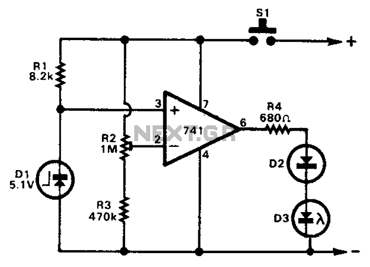
The 741 operational amplifier can function as a voltage comparator. It features a non-inverting input and a Zener-controlled voltage source, with a reference voltage set at 5.1V. Resistor R2 is used to adjust the in-phase input voltage to half...
The TDA7088T can be used in mono portable and pocket radios. This is a bipolar integrated circuit. Here is one of the application circuit diagrams. The TDA7088T is a versatile bipolar integrated circuit designed specifically for mono FM radio applications,...
This simple circuit drives six LEDs in a "Knightrider scanner mode." Power consumption primarily depends on the type of LEDs used, especially if a 7555 (555 CMOS version) is utilized. The circuit operates by sequentially illuminating the LEDs to create...
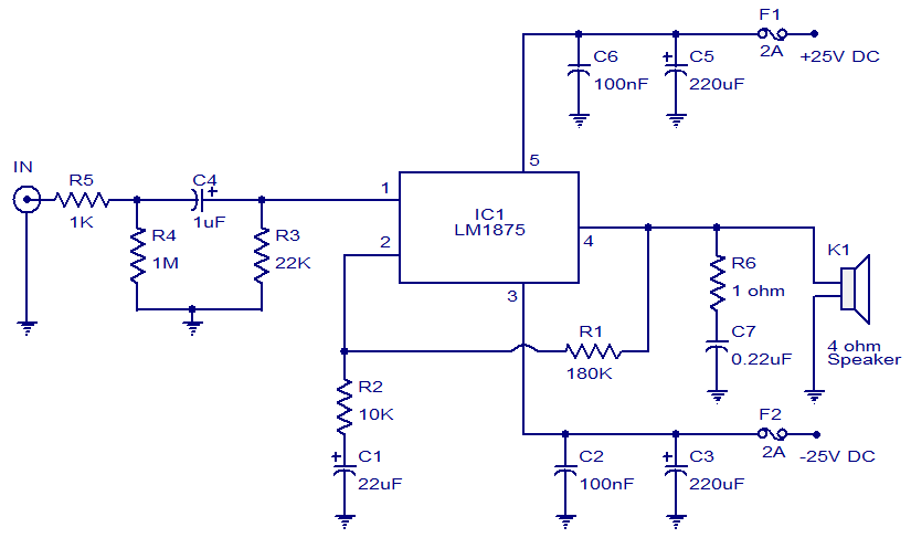
This weblog focuses on electronic circuit schematics, PCB design, DIY kits, and electronic project diagrams. The featured project is a 20W audio amplifier circuit based on the LM1875 audio amplifier IC from National Semiconductors. With a 25V power supply,...
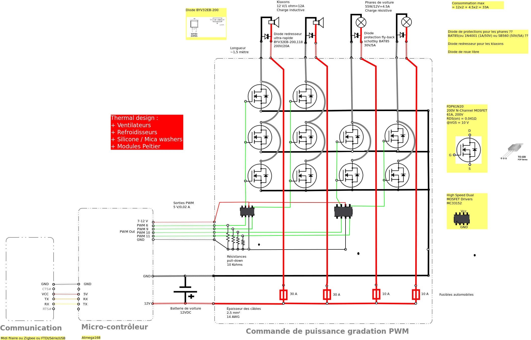
Past experiences were quite challenging due to the inductive nature of car horns, which require 12A of current, with peak demands reaching 20 to 30A. The current electronic system lacks reliability, given the high intensity. There is a need...
This is a circuit diagram for a fuse monitor circuit indicator. This very simple circuit utilizes only two components: a single resistor and an LED. This circuit provides a visual indication when the fuse has blown. LED1 typically remains...