
Car Headlight Alarm
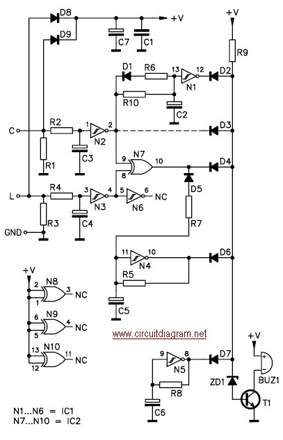
The car headlight alarm circuit is designed to prevent battery drain by ensuring that the vehicle's lights are automatically turned off after the ignition is switched off. This is particularly useful in preventing situations where the headlights or side lights are inadvertently left on, leading to a dead battery.
The circuit typically consists of a relay, a timer, and a few essential components such as resistors and capacitors. When the ignition switch is turned off, the circuit is activated. The relay acts as a switch that controls the power supply to the headlights. A timer can be integrated to provide a delay, allowing the driver to exit the vehicle and close the doors before the lights are turned off.
The configuration can be adjusted to provide an audible alert to the driver if the headlights remain on for an extended period after the ignition is switched off. This feature can be achieved by adding a buzzer or an LED indicator to the circuit.
To summarize, the circuit is beneficial for enhancing vehicle safety and convenience by ensuring that the lights are disabled when the vehicle is not in use, thus mitigating the risk of battery depletion and ensuring reliable vehicle operation. The design can be implemented with standard electronic components, making it a cost-effective solution for vehicle owners.This car headlight alarm circuit can be set for one or two functions: First , to indicate that the head lights (or the side lights) should be switched off after switching off the ignition contact. With this circuit, there should be no dead.. 🔗 External reference
Related Circuits
This simple alarm timer circuit is constructed using a 4060 integrated circuit, which features a stable oscillator with a relatively wide frequency range. The alarm timer circuit utilizes the CD4060 IC, which combines a low-frequency oscillator and a binary counter....
Most cars do not have delayed interior lights. The circuit presented can rectify this issue by gradually switching the interior lights of a car on and off. This feature facilitates tasks such as locating the ignition keyhole after the...
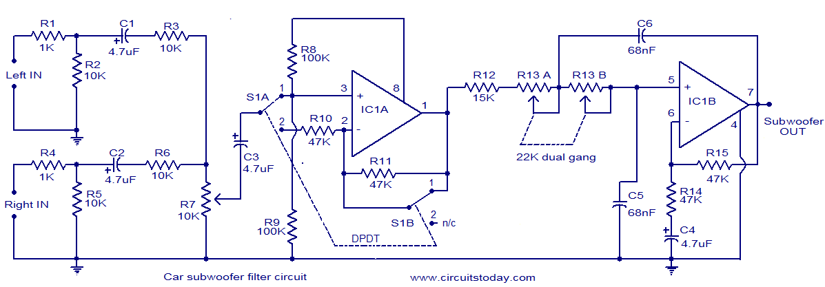
The circuit diagram illustrates a simple subwoofer filter designed to operate with a 12V DC supply, making it particularly useful for automobile subwoofer applications. This circuit functions as a low pass filter, with an adjustable pass frequency ranging from...
The loudspeaker is designed to fit within a fixed enclosure, with its outer diameter matching the diameter of the paper tube for proper installation. The speaker is mounted on wood, with a wooden brush applied to the upper chamber,...
Whenever I'm in the car listening to my favourite CD, it always happens - my batteries go dead. To solve that problem, I built this extremely simple regulator circuit. It steps down the 12V from the lighter socket to...
This LED (Light Emitting Diode) display consists of 10 LEDs to indicate the level of an input signal. If the signal is low, only LED #1 will light up. As the signal level increases, the illuminated dot will progress...