
Car Interior Lights Delay
The circuit operates by integrating a simple yet effective mechanism involving two transistors, T1 and T2, along with a capacitor (C1) and resistors (R3, R5). When the car door is opened, the door switch creates a closed circuit that allows current to flow to the base of T1, which is configured in a common-emitter configuration. This action turns T1 off, allowing the capacitor C1 to charge through R3 and the diode D1. The charging of C1 causes the voltage at the gate of T2 to rise, turning it on and illuminating the interior lights.
The gradual fading of the lights is achieved through the controlled discharge of C1 via R5. The resistance value of R5 determines the rate at which C1 discharges, thereby controlling the duration the interior lights remain on after the door is closed. By adjusting R3, the charging rate of C1 can also be modified, allowing for customization of the delay before the lights turn on.
The choice of the n-channel MOSFET, such as the BUZ74, is crucial as it must support the voltage levels present in automotive applications. The MOSFET acts as a switch that handles the load of the interior lights, ensuring that the circuit can operate reliably without overheating or failing under normal conditions.
In summary, this circuit provides a practical solution for enhancing the functionality of automotive interior lighting by introducing a delay feature that improves user convenience. The design is straightforward, making it accessible for implementation in various vehicle models with minimal modifications to existing wiring.Most cars do not have delayed interior lights. The circuit presented can put this right. It switches the interior lights of a car on and off gradually. This makes it a lot easier, for instance, to find the ignition keyhole when the lights have gone off after the car door has been closed. Since the circuit must be operated by the door switch, a sli ght intervention in the wiring of this switch is unavoidable. When the car door is opened, the door switch closes the lights circuit to earth. When the door is closed (and the switch is open), transistor T1, whose base is linked to the switch, cuts off T2, so that the interior light remains off. When the switch closes (when the door is opened), the base of T1 is at earth level and the transistor is off.
Capacitor C1 is charged fairly rapidly via R3 and D1, whereupon T2 comes on so that the interior light is switched on. When the door is closed again, T1 conducts and stops the charging of C1. However, the capacitor is discharged fairly slowly via R5, so that T2 is not turned off immediately. This ensures that the interior light remains on for a little while and then goes out slowly. The time delays may be varied quite substantially by altering the values of R3, R5, and C1. Circuit IC2 may be one of many types of n-channel power MOSFET, but it should be able to handle drain-source voltages greater than 50 V.
In the proto-type, a BUZ74 is used which can handle D-S voltages of up to 500 V. 🔗 External reference
Related Circuits
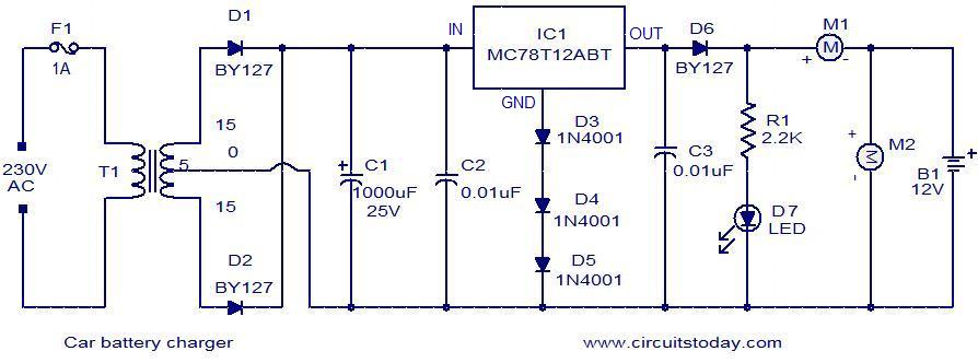
Below is a simple circuit designed for charging car batteries. This circuit includes the capability to monitor both the charging current and voltage. It utilizes the IC MC78T12ABT from Freescale, which is essentially a 7812 in a TO-3 package...
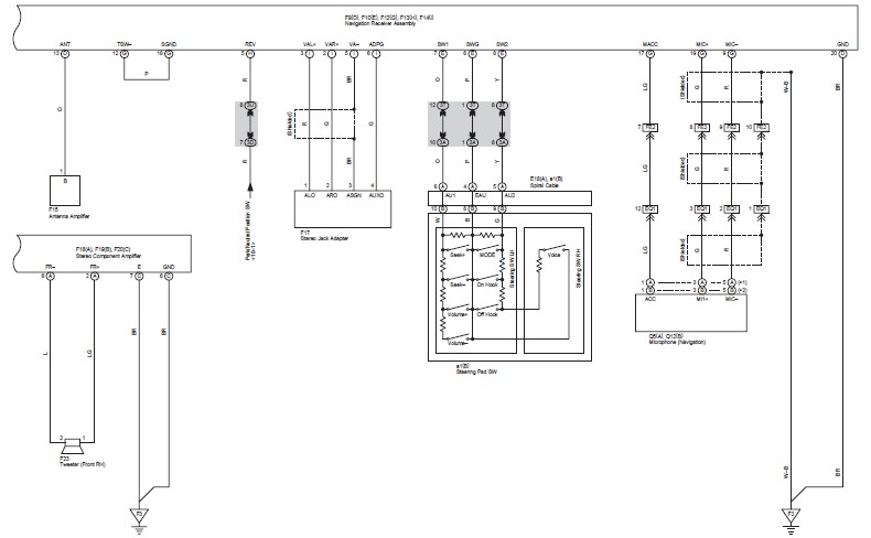
This document contains the wiring diagram for the 2007 Toyota Camry, specifically for the GSV40 and ACV40 series. It details the electrical circuits present in the vehicles, categorizing them by system for clarity. The wiring for each system is...
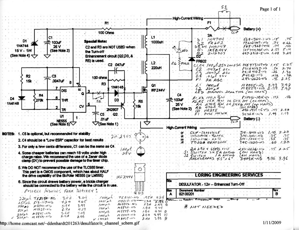
After a year of observing and admiring various projects, a decision was made to create a personal project. The project aims to design an electronic circuit that incorporates various components to achieve a specific functionality. The schematic will typically include...
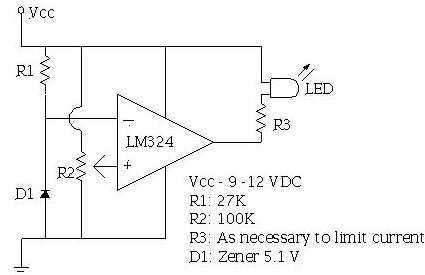
An ECU must have a way to monitor battery voltage. Here is a simple op-amp based circuit which will illuminate the LED when the battery voltage drops to a certain level. The turn-on point is set with R2. You...
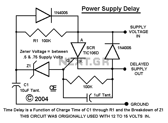
I had designed up an oscillator with a Power Output circuit. Problem was when power was applied to the entire circuit, the output of the Oscillator gave a Momentary Spike into the output circuit. Thus Driving it full on...
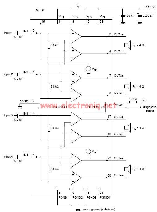
This electronic circuit diagram represents an audio power amplifier utilizing the TDA8571J integrated circuit. It is a class-B output amplifier configured in a BTL (Bridge-Tied Load) arrangement, featuring four amplifiers, each with a gain of 34 dB. The main...
Warning: include(partials/cookie-banner.php): Failed to open stream: Permission denied in /var/www/html/nextgr/view-circuit.php on line 713
Warning: include(): Failed opening 'partials/cookie-banner.php' for inclusion (include_path='.:/usr/share/php') in /var/www/html/nextgr/view-circuit.php on line 713