
Car Park Aid Circuit
The Park Aid system is designed to assist users in parking by providing visual feedback on the proximity of obstacles. The circuit operates using infrared (IR) technology, which is effective for indoor applications where direct line-of-sight is often available.
The three LEDs serve as indicators, illuminating in response to varying distances detected by the IR sensor. The resistors included in the circuit are essential for controlling the current flowing through the LEDs and other components, ensuring that they operate within safe limits.
Resistor R1, with a value of 10K ohms, is likely used for biasing purposes, while the 1K ohm resistors (R2, R5, R6, R9) may be used in various parts of the circuit to stabilize the voltage levels. R3, a 33 ohm resistor, may be used to limit the current in specific sections of the circuit, preventing damage to sensitive components. The 1M ohm resistors (R4, R11) can serve as pull-down or pull-up resistors, ensuring that the inputs to the circuit are at a defined state when not actively driven. R7, with a resistance of 4.7K ohms, and R8, at 1.5K ohms, also play roles in current limiting and voltage division as necessary.
In summary, this Park Aid circuit is a straightforward yet effective design that leverages infrared technology and LED indicators to provide users with a visual representation of distance to obstacles, enhancing safety and convenience during parking maneuvers.Park Aid Three LEDs signal bumper-barrier distance Infra-red operation, indoor use Circuit diagram: Parts: R1 10K 1/4W Resistor R2,R5,R6,R9 1K 1/4W Resistors R3 33R 1/4W Resistor R4,R11 1M 1/4W Resistors R7 4K7 1/4W Resistor R8 1K5 1/4W Res.. 🔗 External reference
Related Circuits
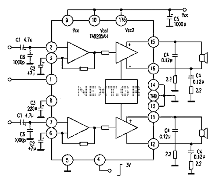
A Mitsubishi Pajero car audio system is experiencing a silent fault, while other features remain operational. The issue is traced to a damaged amplifier IC, specifically the TA8205AH. This integrated circuit, produced by Toshiba, is a dual-channel audio power...
The circuit includes a loudness compensation control terminal at pin 7, which, when combined with the DC control voltage, forms a simple loudness compensation mechanism that enhances bass response. When the loudness control switch is in the OFF position,...
There have been several requests for a quiz circuit, leading to the development of a design featuring four inputs that can be easily modified. This circuit employs four integrated circuits (ICs) and includes four input circuits with independent outputs,...
This project has two features. It will let you know when a single phone is using the line and also when two phones are on the line! The green LED indicates the first phone and the red LED indicates...
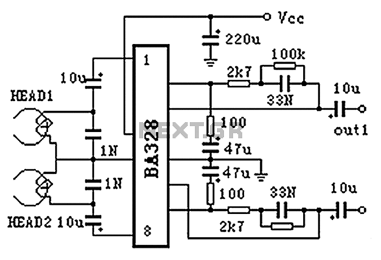
The BA328 is a dual preamplifier circuit designed with minimal external components, facilitating straightforward installation within a single 8-pin DIP package. The circuit features a wide operating voltage range, low noise levels, and high open-loop gain, ensuring good balance...
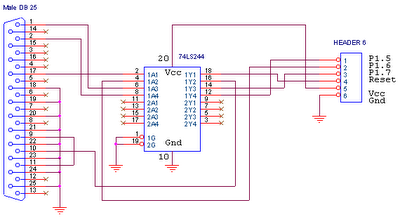
This circuit is designed for use with ATMEL Microcontroller ICs, specifically the AT89Sxx and ATMEGA series. It operates using the MISO, MOSI, SCK, and RESET signals. This circuit serves as a foundational interface for programming and communication with ATMEL microcontrollers,...