
Car Speed limit Alarm
The circuit operates by detecting electromagnetic pulses generated by the engine sparking plugs, which are captured by a sensor coil (L1). These pulses are essential for determining the engine's RPM, which correlates directly to the vehicle's speed. The first integrated circuit (IC1) acts as a differential amplifier, enhancing the weak signals picked up from the sensor coil. This amplification is crucial for ensuring that the subsequent processing stages receive a strong enough signal to work effectively.
Following the differential amplification, IC2A is employed to further amplify the pulses, ensuring that the signal remains robust throughout the processing chain. The output from IC2A is then fed into a series of inverters (IC2B to IC2F), which serve to square the waveform of the pulses. This squaring is necessary to create a clean digital signal that can be easily interpreted by the next stage of the circuit.
The monostable multivibrator, which is not fully described in the original input, likely serves to generate a timed output pulse when the maximum speed is reached. This output can trigger an audible alert (beeping sound) and activate an LED for visual indication. The design allows the driver to be notified without the need to divert attention from the road, promoting safer driving practices.
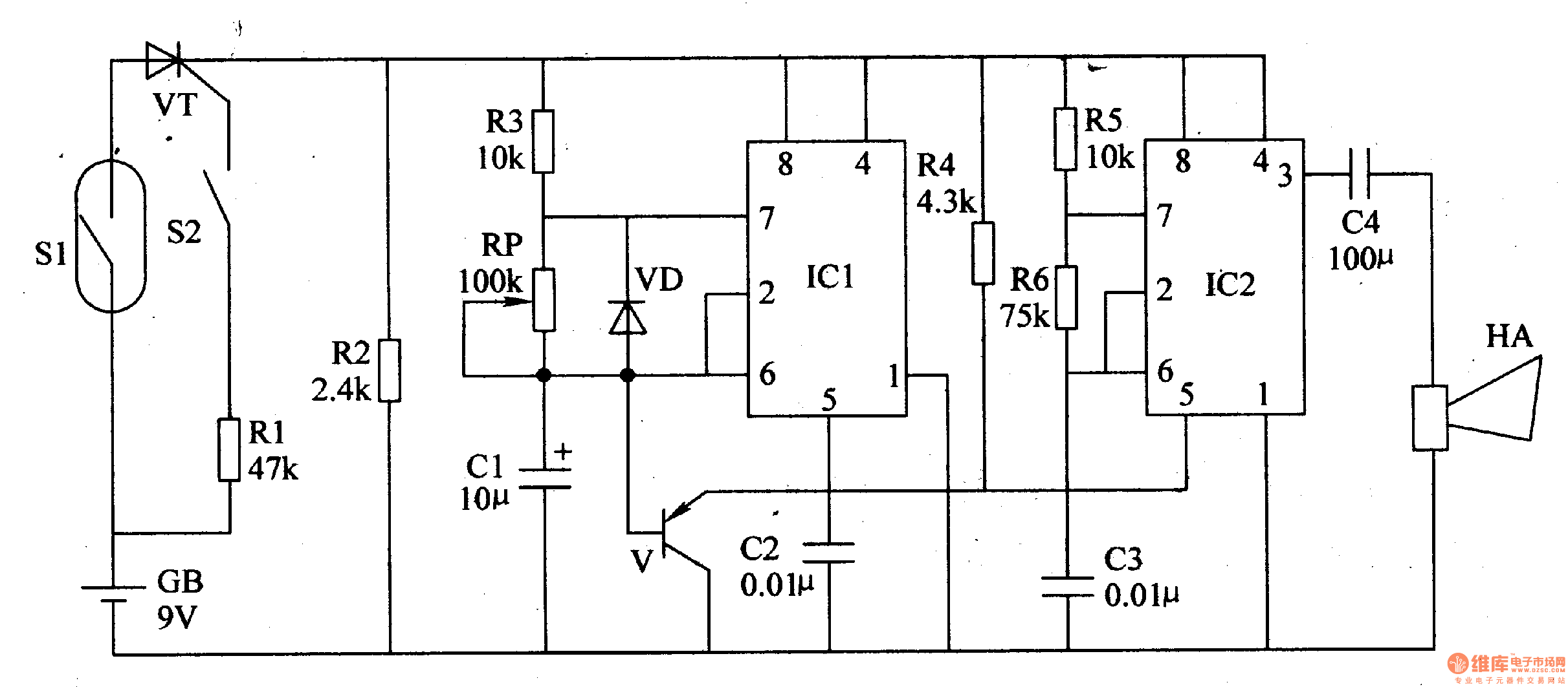
This circuit's unique feature is its ability to function without direct connections to the engine, making installation simpler and reducing potential points of failure. By relying on electromagnetic signals, the system maintains a level of separation from the vehicle's mechanical components, ensuring reliability and ease of use.This circuit has been designed to alert the vehicle driver that he has reached the maximum fixed speed limit (i.e. in a motorway). It eliminates the necessity of looking at the tachometer and to be distracted from driving. There is a strict relation between engine`s RPM and vehicle speed, so this device controls RPM, starting to beep and flashing a LED once per second, when maximum fixed speed is reached.
Its outstanding feature lies in the fact that no connection is required from circuit to engine. IC1 forms a differential amplifier for the electromagnetic pulses generated by the engine sparking-plugs, picked-up by sensor coil L1. IC2A further amplifies the pulses and IC2B to IC2F inverters provide clean pulse squaring. The monostable multivibrator 🔗 External reference
Related Circuits
The Motion Sensor Switch circuit is an automatic water sprinkler controlled by a motion sensor, with the option to incorporate an alarm or light function. Before starting the construction, it is advisable to contact a local electronics component vendor...
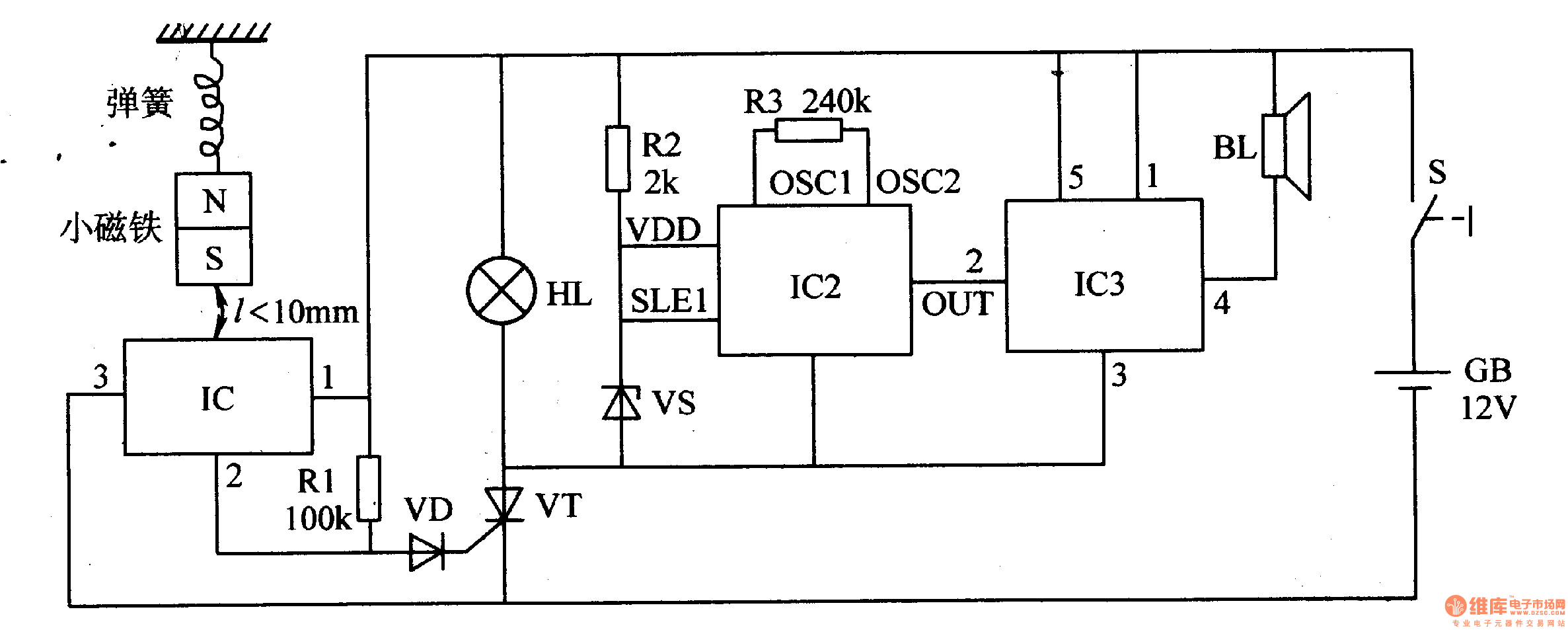
When the switch is activated, the seismic alarm enters a detection mode. In the absence of an earthquake, pin 3 of IC1 outputs a low signal, resulting in the disconnection of VT, which keeps the alarm circuit inactive. Upon...
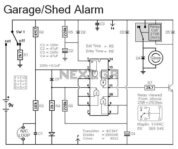
This is a simple single-zone burglar alarm circuit. Its features include automatic exit and entry delays. It is designed to be used with the usual types of normally-closed input devices such as magnetic reed contacts, micro switches, foil tape,...
This article introduces a motorcycle anti-theft alarm that utilizes the 555 timer integrated circuit. The alarm is activated when a thief attempts to move the motorcycle vertically. The circuit consists of a trigger circuit and an alarm circuit, as...
The concept for this circuit was developed due to issues experienced with a bicycle's wireless speedometer. This device comprises two components: the cycle computer and a transmitter mounted on the front fork. A small magnet is affixed to the...
This circuit is designed for use with inductive pick-up elements and dynamic microphones. Most soundcards feature a line input and a dedicated input for electret (condenser) microphones. To connect an inductive tape recorder head or a dynamic microphone, an...