
Car Tachometer with 555 IC
The circuit described involves a timer that receives pulse signals from distributor points, which are likely part of an ignition system in an automotive or similar application. The timer is responsible for processing these pulses and determining when to activate its output signal.
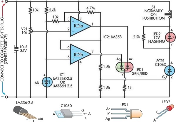
When the timer output is in a high state, it allows current to flow through a resistor, denoted as R6. This resistor is crucial as it helps to limit the current to a safe level for the meter, referred to as Meter M. The meter is designed to display a calibrated reading, which could represent various parameters such as voltage, current, or another measurement relevant to the system's operation.
The interaction between the timer and Meter M is essential for monitoring the system's performance. The calibrated current flowing through R6 ensures that the meter operates within its specified range, providing accurate readings. This functionality is critical in applications where precise measurements are necessary for system diagnostics or performance tuning.
Further analysis of the circuit may involve examining the specifications of the timer, the characteristics of the pulses being received, and the calibration details of Meter M. Additionally, understanding the role of R6, including its resistance value and power rating, will contribute to the overall reliability and accuracy of the circuit. Properly designed, this system can enhance the monitoring capabilities of the application it serves, ensuring optimal performance and safety.Pulses are received by the timer from the distributor points. When the timer output is high, Meter M receives a calibrated current through R6. The meter don`t.. 🔗 External reference
Related Circuits
The 567 IC tone decoder/detector can be utilized to construct a remote control or intercom system. This circuit is capable of controlling a relay or transmitting an audio signal. The 567 IC is a versatile component often employed in tone...
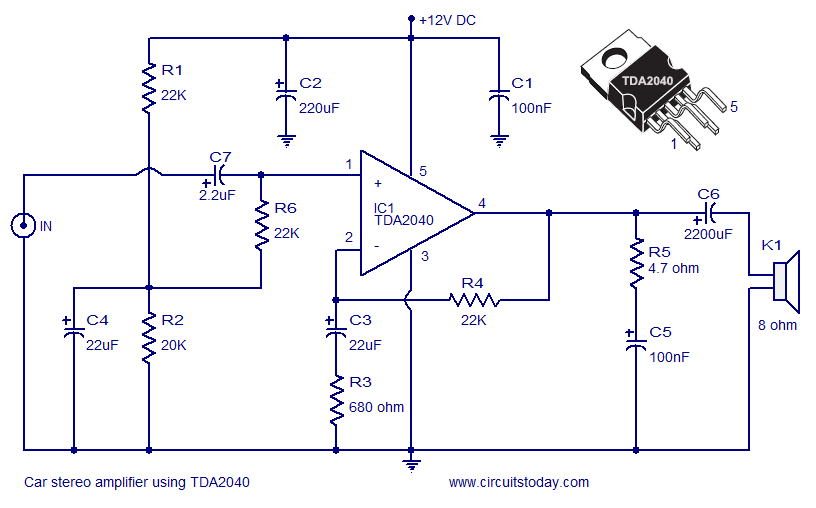
A car stereo amplifier circuit utilizing the TDA2040 is presented here. The TDA2040 is a monolithic integrated audio amplifier that functions in Class AB mode. This integrated circuit features built-in short circuit protection and thermal shutdown capabilities, and it...
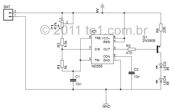
This small device is designed to jam remote controls by directing it at the TV. The circuit utilizes a 555 timer configured as an astable multivibrator, generating a frequency of approximately 38 kHz, which corresponds to the frequency at...
A car battery deteriorates in use, and its life seldom exceeds four years. When new, its voltage may drop to only 2V while cranking the engine. A car battery, typically a lead-acid type, is essential for providing the necessary electrical...
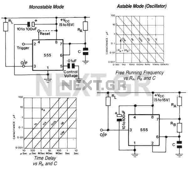
The 555 is a highly stable device for generating accurate time delays or oscillation. Additional terminals are provided for triggering or resetting if desired. In the time delay (monostable) mode of operation, the time is precisely controlled by one...
This beeper circuit utilizes two 555 integrated circuits (ICs) and can operate within a supply voltage range of 5 to 15V DC. It is suitable for applications requiring an alarm or beeping signal. The first IC (IC1) is configured...